Protect PV.630 Operating Instructions
Figure 15 Serial D-sub connector X5
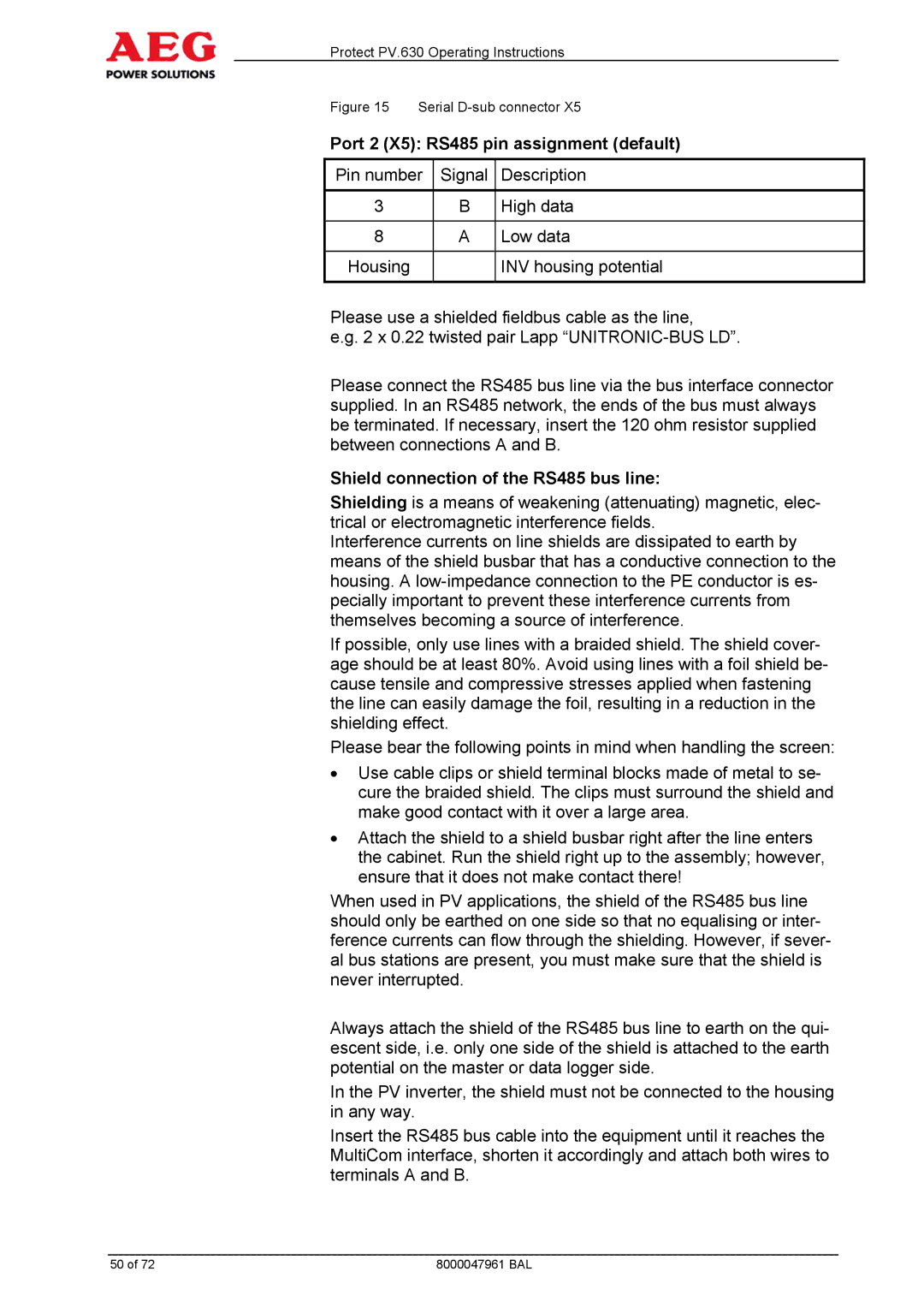
Port 2 (X5): RS485 pin assignment (default)
Pin number | Signal | Description |
|
|
|
3 | B | High data |
|
|
|
8 | A | Low data |
|
|
|
Housing |
| INV housing potential |
|
|
|
Please use a shielded fieldbus cable as the line,
e.g. 2 x 0.22 twisted pair Lapp
Please connect the RS485 bus line via the bus interface connector supplied. In an RS485 network, the ends of the bus must always be terminated. If necessary, insert the 120 ohm resistor supplied between connections A and B.
Shield connection of the RS485 bus line:
Shielding is a means of weakening (attenuating) magnetic, elec- trical or electromagnetic interference fields.
Interference currents on line shields are dissipated to earth by means of the shield busbar that has a conductive connection to the housing. A
If possible, only use lines with a braided shield. The shield cover- age should be at least 80%. Avoid using lines with a foil shield be- cause tensile and compressive stresses applied when fastening the line can easily damage the foil, resulting in a reduction in the shielding effect.
Please bear the following points in mind when handling the screen:
∙Use cable clips or shield terminal blocks made of metal to se- cure the braided shield. The clips must surround the shield and make good contact with it over a large area.
∙Attach the shield to a shield busbar right after the line enters the cabinet. Run the shield right up to the assembly; however, ensure that it does not make contact there!
When used in PV applications, the shield of the RS485 bus line should only be earthed on one side so that no equalising or inter- ference currents can flow through the shielding. However, if sever- al bus stations are present, you must make sure that the shield is never interrupted.
Always attach the shield of the RS485 bus line to earth on the qui- escent side, i.e. only one side of the shield is attached to the earth potential on the master or data logger side.
In the PV inverter, the shield must not be connected to the housing in any way.
Insert the RS485 bus cable into the equipment until it reaches the MultiCom interface, shorten it accordingly and attach both wires to terminals A and B.
50 of 72 | 8000047961 BAL |
