Preparing the Oscilloscope for Use
To connect the oscilloscope probes
To connect the oscilloscope probes
1Connect the Agilent 10074C
Maximum input voltage for analog inputs:
CAT I 300 Vrms, 400 Vpk
CAT II 100 Vrms, 400 Vpk
with 10074C 10:1 probe: CAT I 500 Vpk, CAT II 400 Vpk
2Connect the retractable hook tip on the probe tip to the circuit point of interest. Be sure to connect the probe ground lead to a ground point on the circuit.
The probe ground lead is connected to the oscilloscope chassis and the ground wire in the power cord. If you need to connect the ground lead to a point in the circuit that cannot be grounded to power ground, consider using a differential probe.
To compensate your probe
You should compensate you probes to match their characteristics to the oscilloscope. A poorly compenstated probe can introduce measurement errors. To compensate a probe, follow these steps:
1Connect the probe from channel 1 to the Probe Comp signal on the lower- right corner of the front panel.
2Press Autoscale.
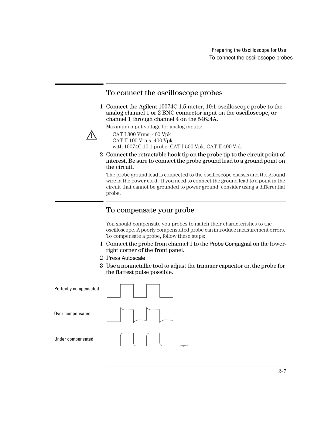
3Use a nonmetallic tool to adjust the trimmer capacitor on the probe for the flattest pulse possible.
Perfectly compensated
Over compensated
Under compensated
comp.cdr