Testing Performance
To verify digital channel threshold accuracy
1Turn on the test equipment and the oscilloscope. Let them warm up for 30 minutes before starting the test.
2Set up the oscilloscope calibrator.
a Set the oscilloscope calibrator to provide a DC offset voltage at the Channel 1 output.
b Use the multimeter to monitor the oscilloscope calibrator DC output voltage.
3Use either method 1 or method 2, described in the following, to connect the digital channels for testing.
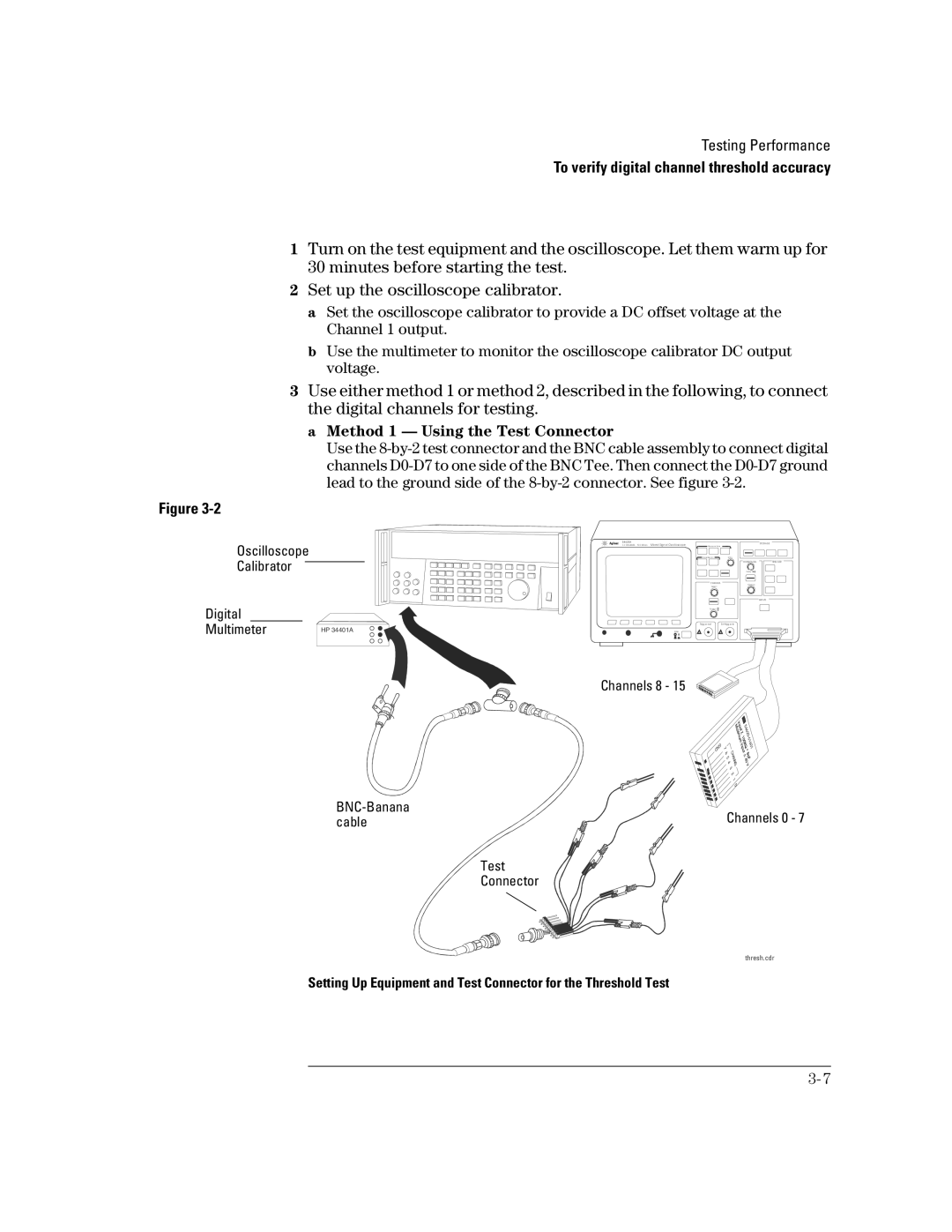
a Method 1 — Using the Test Connector
Use the
Figure
Oscilloscope
Calibrator
Digital |
|
Multimeter | HP 34401A |
|
5 46 2 0 A
1 6 C H AN N EL 5 0 0 M S a/s M ixe d Signal O sc illo sc o pe
Line
STO R A G E
![]()
![]() M e a sure tim e
M e a sure tim e
S a ve/ Re c a ll | E ntry |
| H O RIZO N TA L | TRIG G E R |
| D ela y |
|
C H A N N E L | Tim e/D iv |
|
Sele c t |
|
|
|
| IN P U TS |
Po sitio n |
Trigg er ou t | Ex t trigg er in |
!!
Channels 8 - 15
Channels 0 - 7 | |
cable |
Test
Connector
thresh.cdr
Setting Up Equipment and Test Connector for the Threshold Test