Testing Performance
To verify voltage measurement accuracy
3Use the BNC tee and cables to connect the oscilloscope calibrator /power supply to both the oscilloscope and the multimeter.
4Adjust the output so that the multimeter reading displays the first Volts/div supply setting value in Table
Wait a few seconds for the measurement to settle.
5Press the Y2 softkey, then position the Y2 cursor to the center of the voltage trace using the Entry knob.
The ∆Y value on the lower line of the display should be within the test limits of Table
6Continue to check the voltage measurement accuracy with the remaining Volts/div setting values in Table
7When you are finished checking all of the power supply setting values, disconnect the power supply from the oscilloscope.
8Repeat this procedure for Channels 2, 3, and 4, if applicable on your oscilloscope model.
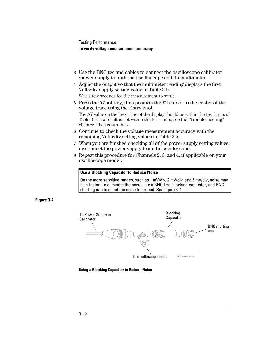
Use a Blocking Capacitor to Reduce Noise
On the more sensitive ranges, such as 1 mV/div, 2 mV/div, and 5 mV/div, noise may be a factor. To eliminate the noise, use a BNC Tee, blocking capacitor, and BNC shorting cap to shunt the noise to ground. See figure
Figure
To Power Supply or | Blocking | |
Capacitor | ||
Calibrator | ||
|
BNC shorting ![]()
![]()
![]() cap
cap
To oscilloscope input