Testing Performance
To construct the test connector
To construct the test connector
The Agilent 54621D/22D
Construct Test Connector only if Test Fixture is not available
The test connector is not required if
Table | Materials Required to Construct the Test Connectors | ||
|
|
|
|
| Description | Recommended Part | Qty |
| BNC (f) Connector | Agilent | 1 |
| Berg Strip, |
| 1 |
| Jumper wire |
|
|
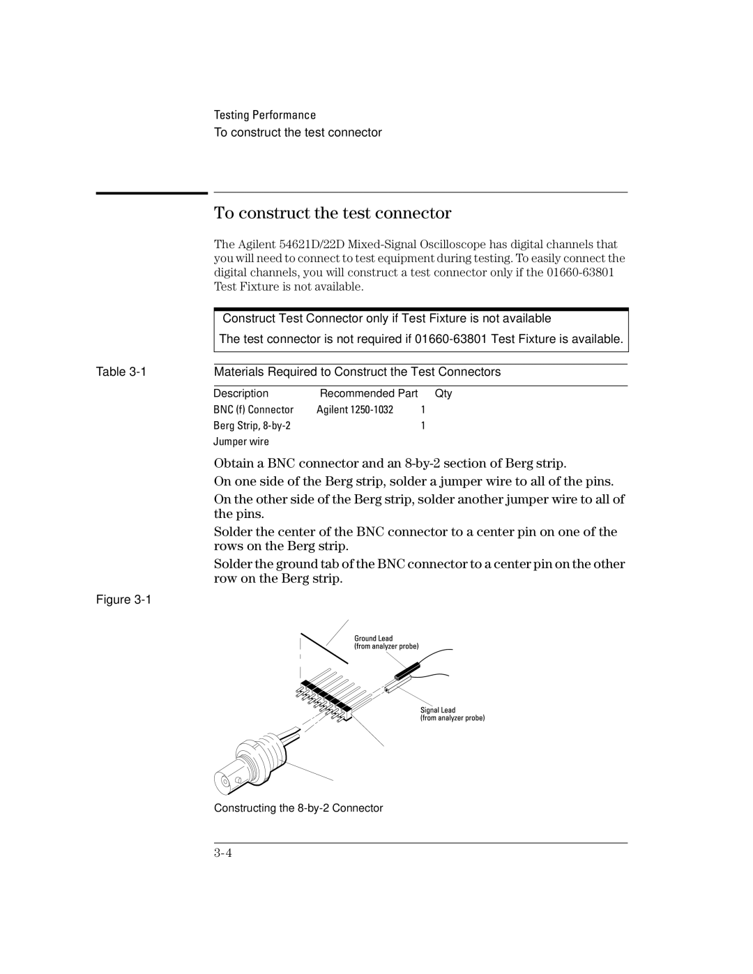
1Obtain a BNC connector and an
2On one side of the Berg strip, solder a jumper wire to all of the pins.
3On the other side of the Berg strip, solder another jumper wire to all of the pins.
4Solder the center of the BNC connector to a center pin on one of the rows on the Berg strip.
5Solder the ground tab of the BNC connector to a center pin on the other row on the Berg strip.
Figure