Testing Performance
To verify trigger sensitivity
To verify trigger sensitivity
This test verifies the trigger sensitivity. In this test, you will apply 25 MHz to the oscilloscope. You will then decrease the amplitude of the signal to the specified levels, and check to see if the oscilloscope is still triggered. You will then repeat the process at the upper bandwidth limit.
Test limits for the Internal trigger:
1 mV to 5 V/div (dc to max bandwidth): greater of 0.35 div or 2.5
Test limits for the External trigger:
dc to 25 MHz: <75
25 MHz to max bandwidth: <150
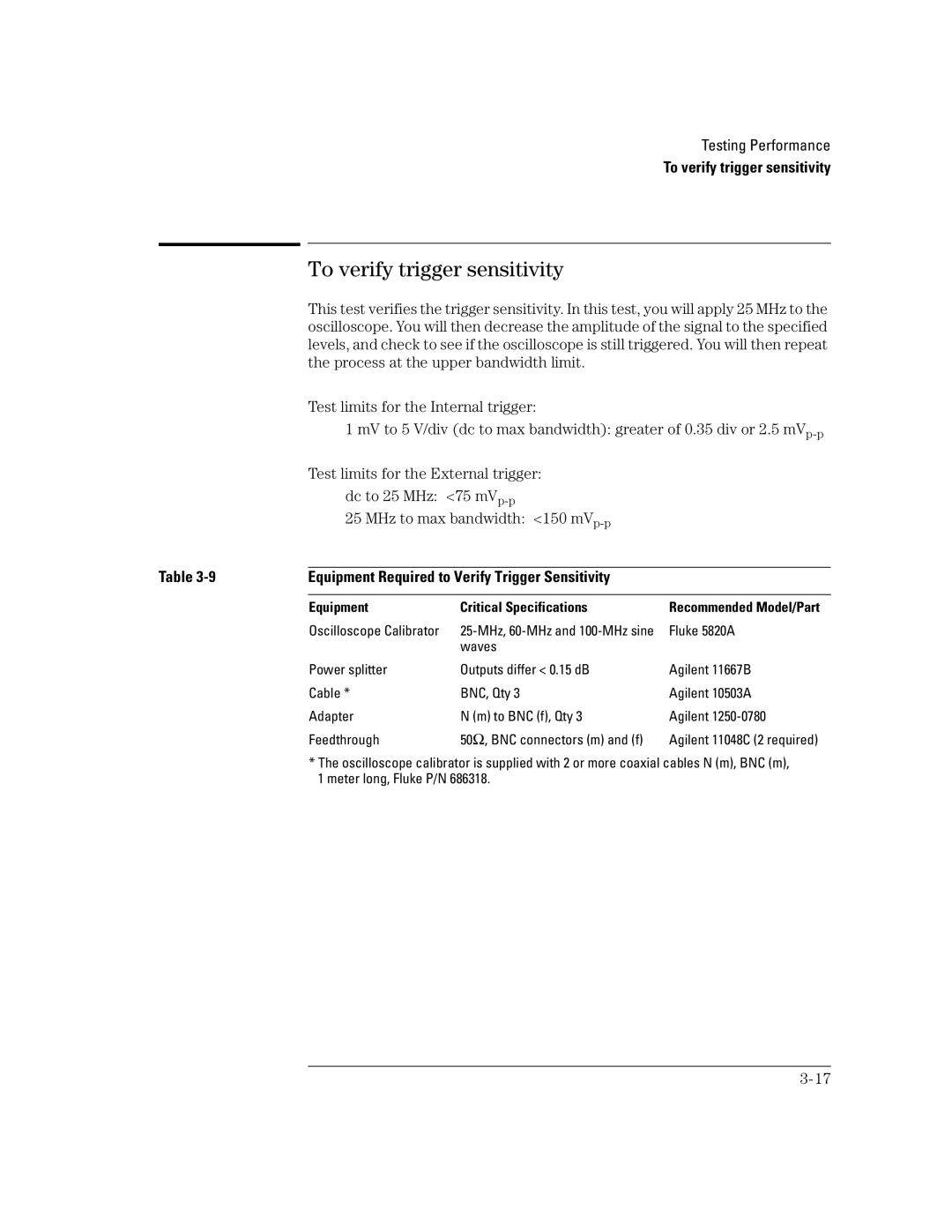
Table | Equipment Required to Verify Trigger Sensitivity |
| |
|
|
|
|
| Equipment | Critical Specifications | Recommended Model/Part |
| Oscilloscope Calibrator | Fluke 5820A | |
|
| waves |
|
| Power splitter | Outputs differ < 0.15 dB | Agilent 11667B |
| Cable * | BNC, Qty 3 | Agilent 10503A |
| Adapter | N (m) to BNC (f), Qty 3 | Agilent |
| Feedthrough | 50Ω, BNC connectors (m) and (f) | Agilent 11048C (2 required) |
*The oscilloscope calibrator is supplied with 2 or more coaxial cables N (m), BNC (m), 1 meter long, Fluke P/N 686318.
