Preparing the Oscilloscope for Use
To use the digital probes (mixed-signal oscilloscope only)
To use the digital probes (mixed-signal oscilloscope only)
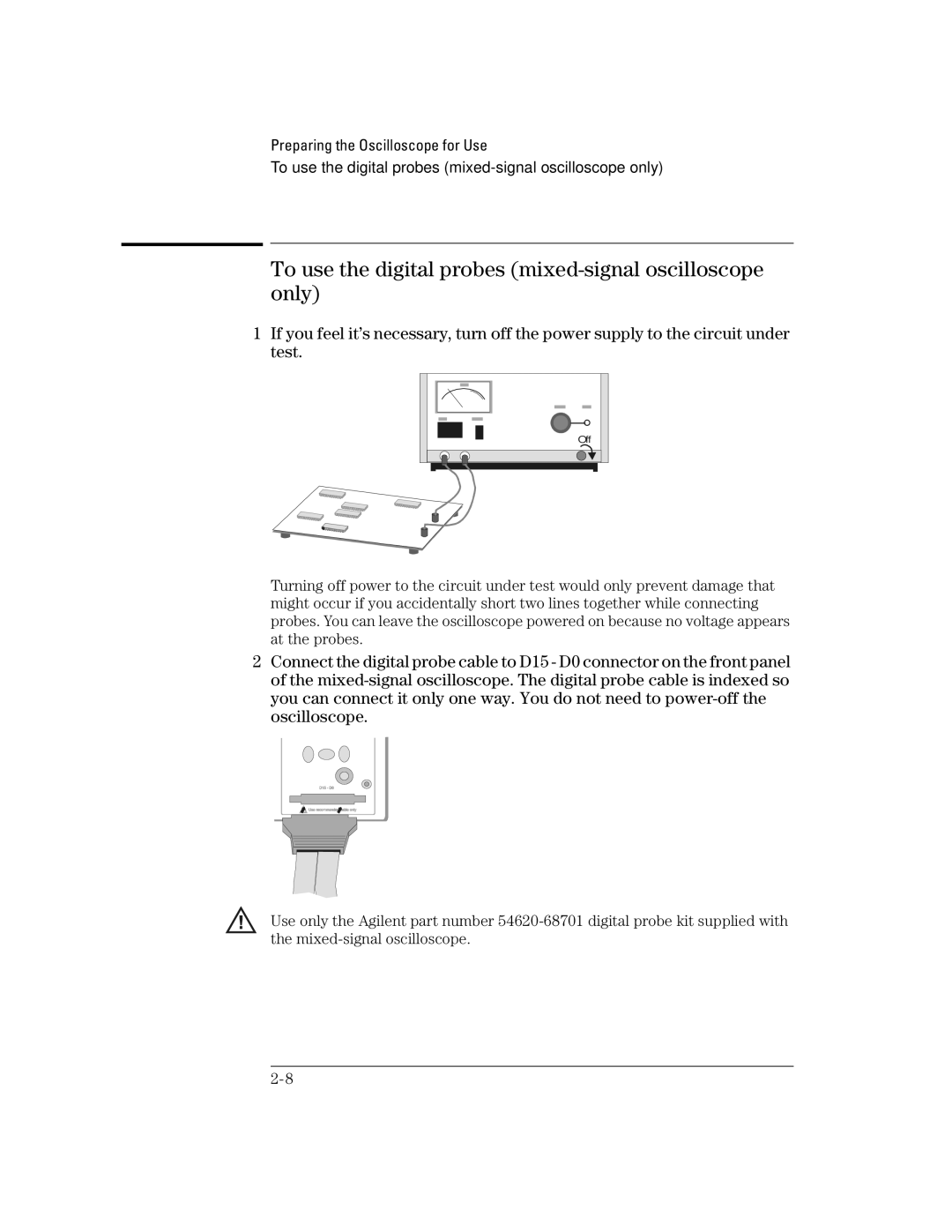
1If you feel it’s necessary, turn off the power supply to the circuit under test.
Off
Turning off power to the circuit under test would only prevent damage that might occur if you accidentally short two lines together while connecting probes. You can leave the oscilloscope powered on because no voltage appears at the probes.
2Connect the digital probe cable to D15 - D0 connector on the front panel of the
Use only the Agilent part number