Installation
Connecting the Probe
CAUTION Do not touch the probe connector pins or the cable connector pins. Static discharge may damage equipment.
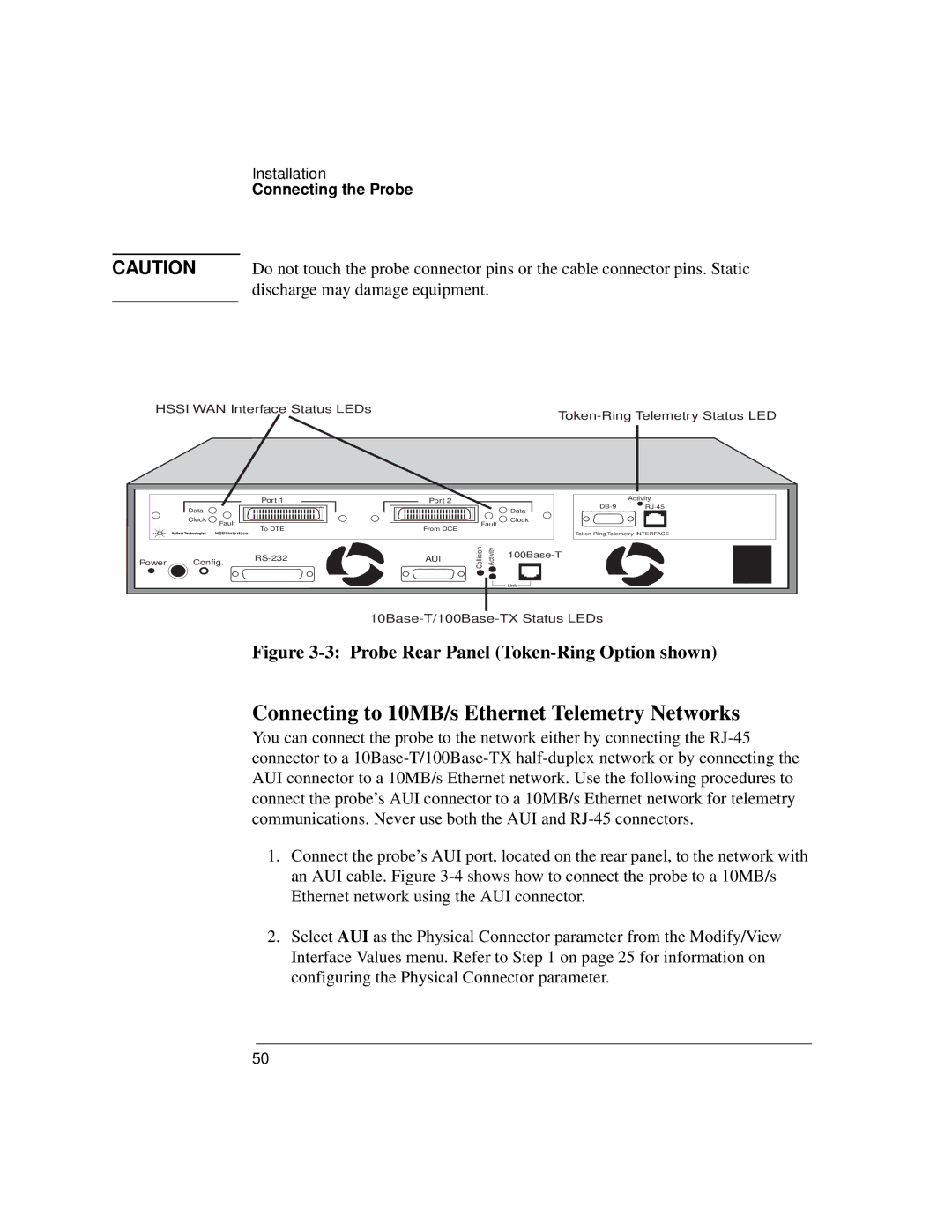
HSSI WAN Interface Status LEDs
| Port 1 | Port 2 |
Data |
| Data |
Clock | Fault | Clock |
| Fault | |
| To DTE | From DCE |
| HSSI Interface |
|
Power | Config. | AUI | Collision | Activity | ||
|
| |||||
|
|
| ||||
|
|
|
|
|
Activity
Figure 3-3: Probe Rear Panel (Token-Ring Option shown)
Connecting to 10MB/s Ethernet Telemetry Networks
You can connect the probe to the network either by connecting the
1.Connect the probe’s AUI port, located on the rear panel, to the network with an AUI cable. Figure
2.Select AUI as the Physical Connector parameter from the Modify/View Interface Values menu. Refer to Step 1 on page 25 for information on configuring the Physical Connector parameter.
50