Thermal Design Guide for Socket F (1207) Processors | 32800 Rev. 3.02 August 2006 |
Depending on the system features and layout, more space around the socket may be available for the thermal solution than is shown in Figure 4 on page 21. This space permits heat sink designs with better thermal performance.
Appendix B on page 45 shows a complete, detailed set of
4.2Thermal Solution Design Requirements
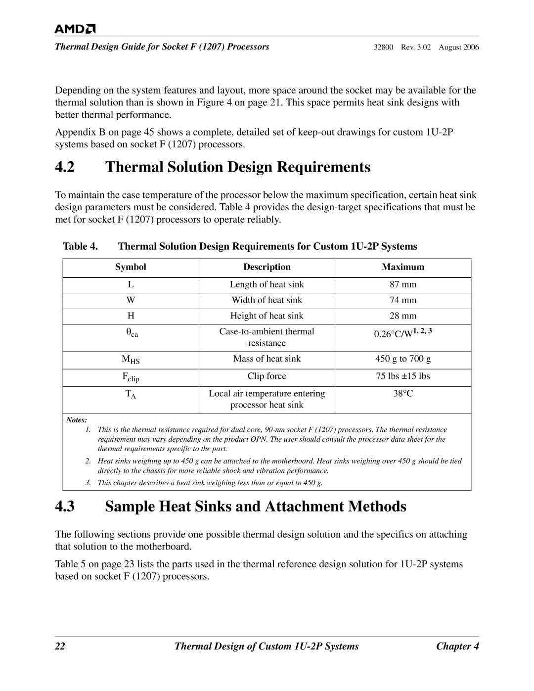
To maintain the case temperature of the processor below the maximum specification, certain heat sink design parameters must be considered. Table 4 provides the
Table 4. | Thermal Solution Design Requirements for Custom | ||
|
|
|
|
| Symbol | Description | Maximum |
|
|
|
|
| L | Length of heat sink | 87 mm |
|
|
|
|
| W | Width of heat sink | 74 mm |
|
|
|
|
| H | Height of heat sink | 28 mm |
|
|
|
|
| θca | 0.26°C/W1, 2, 3 | |
|
| resistance |
|
| MHS | Mass of heat sink | 450 g to 700 g |
| Fclip | Clip force | 75 lbs ±15 lbs |
| TA | Local air temperature entering | 38°C |
|
| processor heat sink |
|
|
|
|
|
Notes: |
|
|
|
1. This is the thermal resistance required for dual core, | |||
requirement may vary depending on the product OPN. The user should consult the processor data sheet for the | |||
thermal requirements specific to the part. |
| ||
2. Heat sinks weighing up to 450 g can be attached to the motherboard. Heat sinks weighing over 450 g should be tied | |||
directly to the chassis for more reliable shock and vibration performance. |
| ||
3. This chapter describes a heat sink weighing less than or equal to 450 g. |
| ||
|
|
|
|
4.3Sample Heat Sinks and Attachment Methods
The following sections provide one possible thermal design solution and the specifics on attaching that solution to the motherboard.
Table 5 on page 23 lists the parts used in the thermal reference design solution for
22 | Thermal Design of Custom | Chapter 4 |