32800 Rev. 3.02 3.00 August 2006 | Thermal Design Guide for Socket F (1207) Processors |
Lifting the heat sink away from the processor can result in damage to the processor contact pads, the socket contacts, or the socket
4.3.3Heat Sink
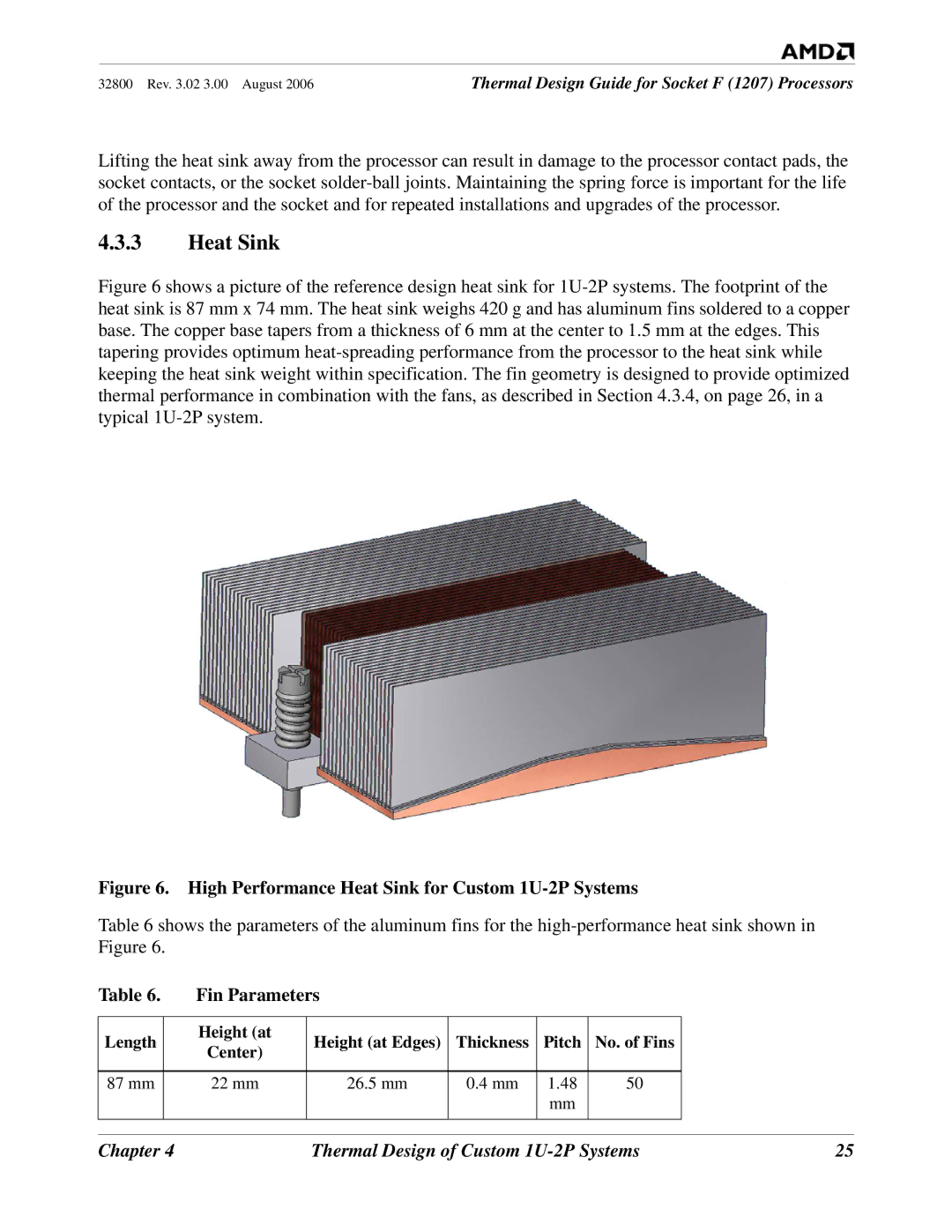
Figure 6 shows a picture of the reference design heat sink for 1U-2P systems. The footprint of the heat sink is 87 mm x 74 mm. The heat sink weighs 420 g and has aluminum fins soldered to a copper base. The copper base tapers from a thickness of 6 mm at the center to 1.5 mm at the edges. This tapering provides optimum heat-spreading performance from the processor to the heat sink while keeping the heat sink weight within specification. The fin geometry is designed to provide optimized thermal performance in combination with the fans, as described in Section 4.3.4, on page 26, in a typical 1U-2P system.
Figure 6. High Performance Heat Sink for Custom 1U-2P Systems
Table 6 shows the parameters of the aluminum fins for the
Table 6. | Fin Parameters |
|
|
|
| |
|
|
|
|
|
|
|
Length | Height (at | Height (at Edges) | Thickness | Pitch | No. of Fins |
|
Center) |
| |||||
|
|
|
|
|
| |
|
|
|
|
|
|
|
87 mm | 22 mm | 26.5 mm | 0.4 mm | 1.48 | 50 |
|
|
|
|
| mm |
|
|
|
|
|
|
|
|
|
|
|
|
|
|
|
|
Chapter 4 | Thermal Design of Custom | 25 |