32800 Rev. 3.02 August 2006 | Thermal Design Guide for Socket F (1207) Processors |
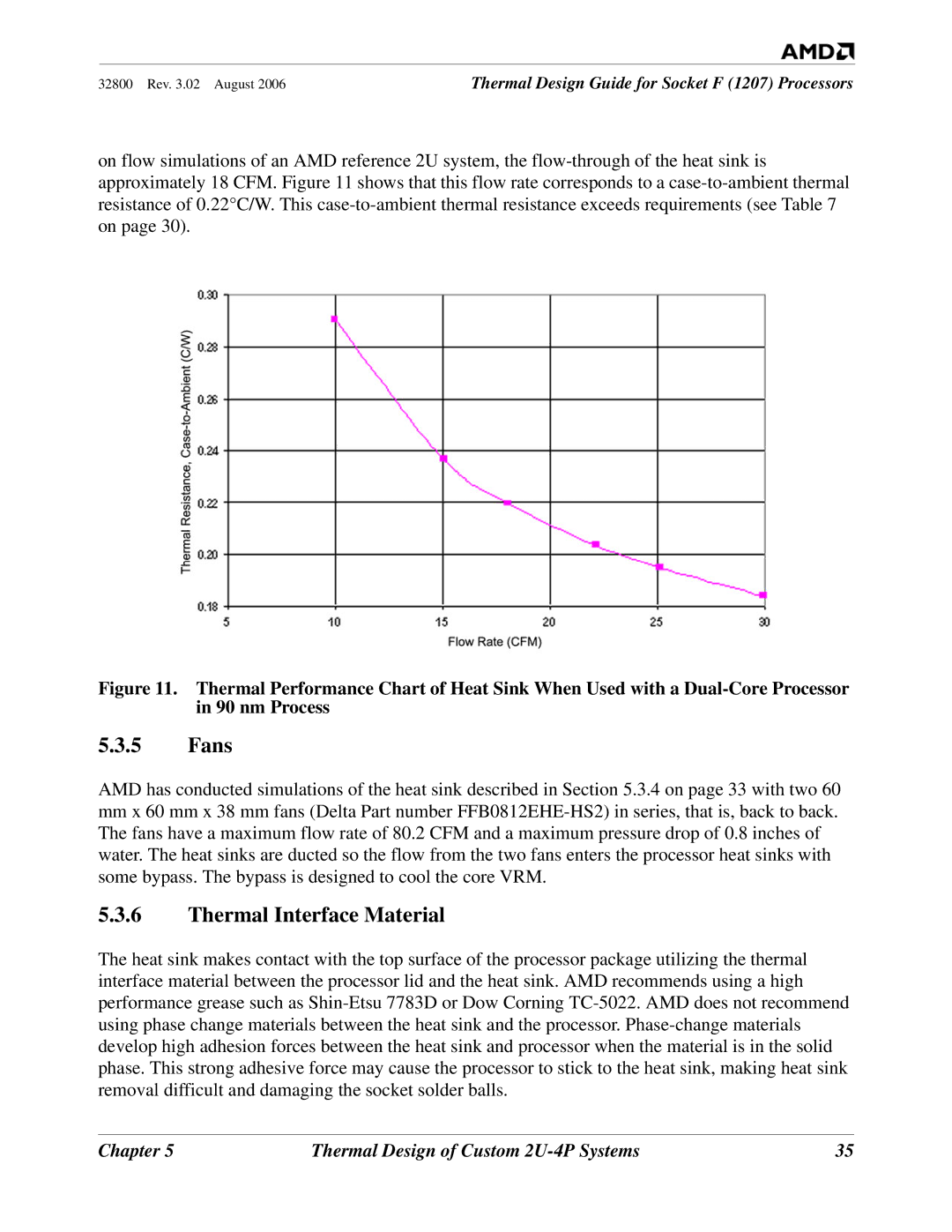
on flow simulations of an AMD reference 2U system, the flow-through of the heat sink is approximately 18 CFM. Figure 11 shows that this flow rate corresponds to a case-to-ambient thermal resistance of 0.22°C/W. This case-to-ambient thermal resistance exceeds requirements (see Table 7 on page 30).
Figure 11. Thermal Performance Chart of Heat Sink When Used with a Dual-Core Processor in 90 nm Process
5.3.5Fans
AMD has conducted simulations of the heat sink described in Section 5.3.4 on page 33 with two 60
mmx 60 mm x 38 mm fans (Delta Part number FFB0812EHE-HS2) in series, that is, back to back. The fans have a maximum flow rate of 80.2 CFM and a maximum pressure drop of 0.8 inches of water. The heat sinks are ducted so the flow from the two fans enters the processor heat sinks with some bypass. The bypass is designed to cool the core VRM.
5.3.6Thermal Interface Material
The heat sink makes contact with the top surface of the processor package utilizing the thermal interface material between the processor lid and the heat sink. AMD recommends using a high performance grease such as Shin-Etsu 7783D or Dow Corning TC-5022. AMD does not recommend using phase change materials between the heat sink and the processor. Phase-change materials develop high adhesion forces between the heat sink and processor when the material is in the solid phase. This strong adhesive force may cause the processor to stick to the heat sink, making heat sink removal difficult and damaging the socket solder balls.
Chapter 5 | Thermal Design of Custom 2U-4P Systems | 35 |