32800 Rev. 3.02 August 2006 | Thermal Design Guide for Socket F (1207) Processors |
5.3.2Spring Clip
The spring clip is designed to apply 75 lbs of force to the center of the heat sink. This force is necessary to help prevent the heat sink from lifting off of the package during shock or vibration- induced events. Lifting the heat sink away from the processor can result in damage to the processor contact pads, the socket contacts, or the socket
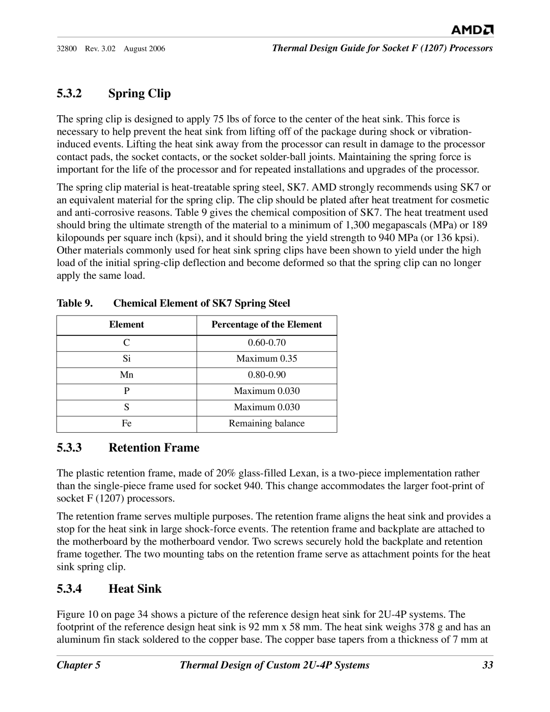
The spring clip material is
Other materials commonly used for heat sink spring clips have been shown to yield under the high load of the initial
Table 9. | Chemical Element of SK7 Spring Steel | |
|
|
|
| Element | Percentage of the Element |
|
|
|
| C | |
|
|
|
| Si | Maximum 0.35 |
|
|
|
| Mn | |
|
|
|
| P | Maximum 0.030 |
|
|
|
| S | Maximum 0.030 |
|
|
|
| Fe | Remaining balance |
|
|
|
5.3.3Retention Frame
The plastic retention frame, made of 20%
The retention frame serves multiple purposes. The retention frame aligns the heat sink and provides a stop for the heat sink in large
5.3.4Heat Sink
Figure 10 on page 34 shows a picture of the reference design heat sink for 2U-4P systems. The footprint of the reference design heat sink is 92 mm x 58 mm. The heat sink weighs 378 g and has an aluminum fin stack soldered to the copper base. The copper base tapers from a thickness of 7 mm at
Chapter 5 | Thermal Design of Custom | 33 |
