Appendix C
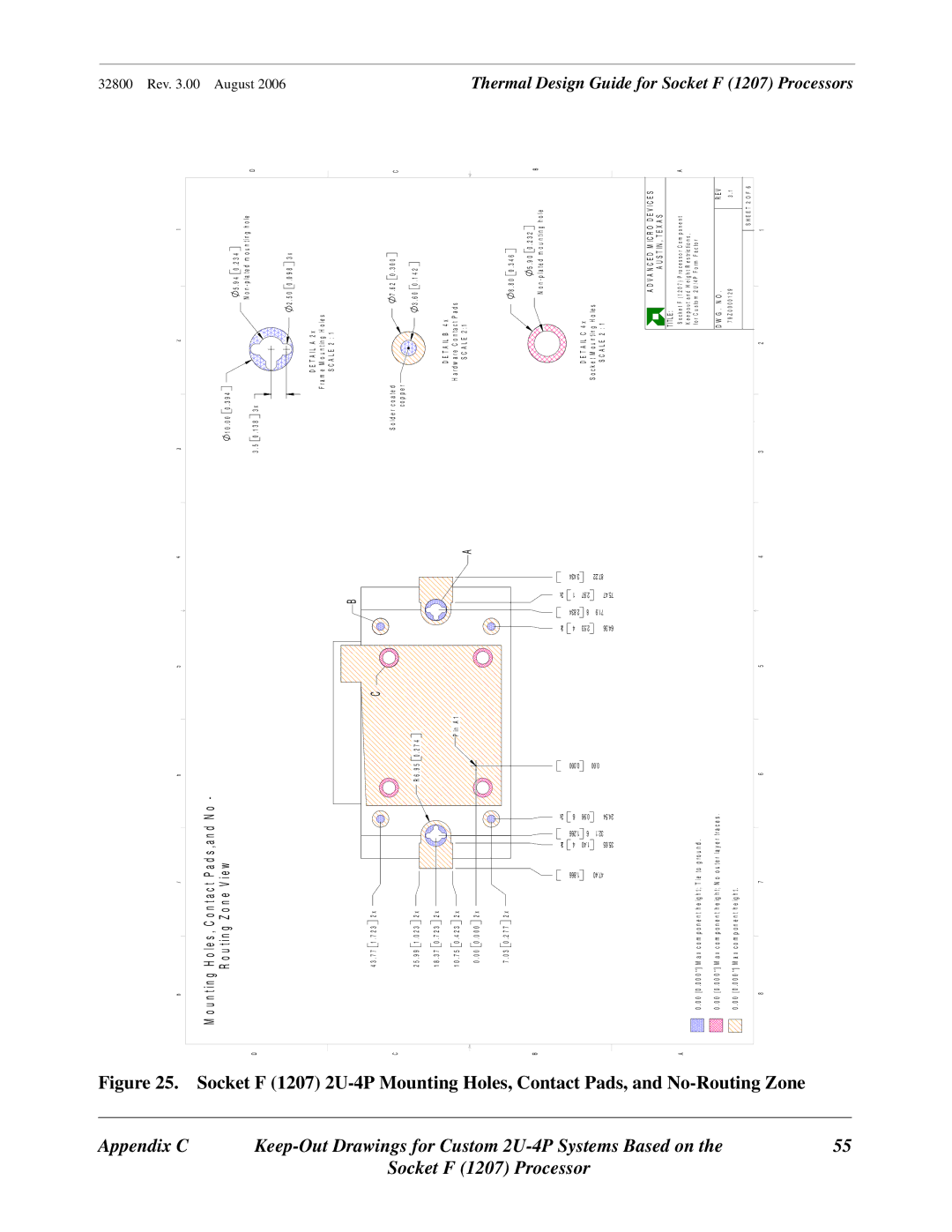
Figure 25.
87654
M o u n t i n g H o l e s , C o n t a c t P a d s , a n d N o -
3 | 2 | 1 |
32800 Rev. 3.00
|
Socket F (1207) 2U
R o u t i n g Z o n e V i e w
D
![]() 1 0 . 0 0
1 0 . 0 0
3 . 5 ![]() 0 . 1 3 8
0 . 1 3 8
0 . 3 9 4 |
|
| 5 . 9 4 |
| 0 . 2 3 4 |
|
| |||||
|
|
|
|
|
|
|
| |||||
3 x |
|
|
| N o n - p l a |
| t e d m o u | n t i n g h o l e | D | ||||
|
| 2 . 5 0 |
| 0 . 0 9 8 | 3 x | |||||||
|
|
|
|
|
|
| ||||||
|
|
|
|
|
|
| ||||||
|
|
|
|
|
|
| ||||||
|
| D E T A I L | A | 2 x |
|
|
| |||||
|
|
|
|
| ||||||||
|
| F r a m e M o u n t i n g H o l e s |
|
|
| |||||||
|
| S C A L E | 2 | : 1 |
|
|
|
|
|
|
| |
August 2006
Socket | Drawings for |
F (1207) Processor | Custom |
| Based on the |
55
-4P Mounting Holes, Contact Pads, and No-Routing Zone
|
|
|
|
|
|
|
|
| B |
|
4 3 . 7 7 | 1 . 7 2 3 | 2 x |
|
|
|
| C |
|
|
|
C |
|
|
|
|
|
|
|
|
|
|
2 5 . 9 9 | 1 . 0 2 3 | 2 x |
|
|
| R 6 . 9 5 | 0 . 2 7 4 |
|
|
|
1 8 . 3 7 | 0 . 7 2 3 | 2 x |
|
|
|
|
|
|
|
|
1 0 . 7 5 | 0 . 4 2 3 | 2 x |
|
|
|
| P i n A 1 |
|
| A |
0 . 0 0 | 0 . 0 0 0 | 2 x |
|
|
|
|
|
|
| |
|
|
|
|
|
|
|
| |||
7 . 0 3 | 0 . 2 7 7 | 2 x |
|
|
|
|
|
|
|
|
B |
|
|
|
|
|
|
|
|
|
|
|
|
| 2x |
| 2x |
| 2x |
| 2x |
|
|
| 1.866 | 4 | 1.266 | 6 | 0.000 | 4 | 2.834 | 1 | 3.434 |
|
| 47.40 | 1.40 | 6 | 0.96 | 0.00 | 2.53 | 8 | 2.97 | 87.22 |
|
| 35.65 | 32.1 | 24.54 | 64.36 | 71.9 | 75.47 | |||
|
|
|
|
|
|
|
A
0 . 0 0 | [ 0 . 0 0 0 ' ' ] M a x c o m p o n e n t h e i g h t ; T i e t o g r o u n d . |
|
|
| ||||||
0 . 0 0 | [ 0 . 0 0 0 ' ' ] | M | a x | c o m | p o n e n t | h e i g h t ; | N o o u t e r l a y e r t r a c e s . |
|
|
|
0 . 0 0 | [ 0 . 0 0 0 ' ' ] | M | a x | c o m | p o n e n t | h e i g h t . |
|
|
|
|
8 |
|
|
|
|
|
| 7 | 6 | 5 | 4 |
S o l d e r c o a t e d |
|
| 7 . 6 2 | 0 . 3 0 0 |
|
|
| C | ||
c o p p e r |
|
|
|
|
|
|
|
|
|
|
|
|
| 3 . 6 0 0 . 1 4 2 |
|
|
|
| |||
D E T A I L | B | 4 x |
|
|
|
|
| |||
H a r d w a r e C o n t a c t P a d s |
|
|
|
|
| |||||
S C A L E | 2 : 1 |
|
|
|
|
|
|
| ||
|
|
| 8 . 8 0 | 0 . 3 4 6 |
|
|
|
| ||
|
|
|
|
|
| 5 . 9 0 |
| 0 . 2 3 2 |
| B |
|
|
|
|
|
|
|
| |||
|
|
|
|
| N o n - p l a t e d m o u n t i n g h o l e | |||||
|
|
|
|
|
| |||||
D E | T A I L | C | 4 x |
|
|
|
|
| ||
S o c k e t M o u n t i n g H o l e s |
|
|
|
|
| |||||
S C A L E | 2 | : 1 |
|
|
|
|
|
|
| |
|
|
|
|
| A D V A N C E D M I C R O D E V I C E S | |||||
|
|
| T IT L E : | A U S T I N , T E X A S |
| |||||
|
|
|
|
|
|
|
| |||
|
|
| S o c k e t F ( 1 2 0 7 ) P r o c e s s o r C o m p o n e n t | A | ||||||
|
|
| K e e p o u t a n d H e i g h t R e s t r i c t i o n s , |
| ||||||
|
|
| f o r C u s t o m 2 U / 4 P F o r m F a c t o r |
| ||||||
|
|
| D W G . N O . |
|
|
|
| R E V | ||
|
|
| 7 9 Z 0 0 0 0 1 2 9 |
|
|
|
| 3 . 1 | ||
|
|
|
|
|
|
|
|
| S H E E T | 2 O F 6 |
3 | 2 |
|
|
|
| 1 |
|
| ||
Thermal Design Guide for Socket F (1207) Processors