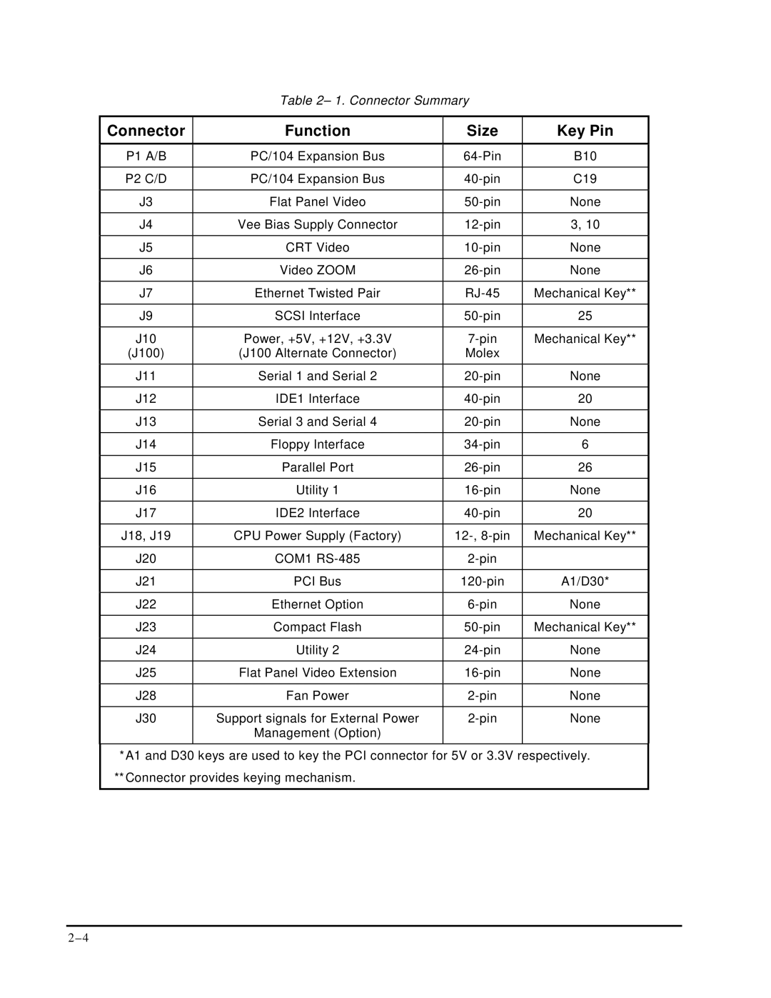
Table 2– 1. Connector Summary
Connector | Function | Size | Key Pin |
P1 A/B | PC/104 Expansion Bus | B10 | |
|
|
|
|
P2 C/D | PC/104 Expansion Bus | C19 | |
|
|
|
|
J3 | Flat Panel Video | None | |
|
|
|
|
J4 | Vee Bias Supply Connector | 3, 10 | |
|
|
|
|
J5 | CRT Video | None | |
|
|
|
|
J6 | Video ZOOM | None | |
|
|
|
|
J7 | Ethernet Twisted Pair | Mechanical Key** | |
|
|
|
|
J9 | SCSI Interface | 25 | |
|
|
|
|
J10 | Power, +5V, +12V, +3.3V | Mechanical Key** | |
(J100) | (J100 Alternate Connector) | Molex |
|
J11 | Serial 1 and Serial 2 | None | |
|
|
|
|
J12 | IDE1 Interface | 20 | |
|
|
|
|
J13 | Serial 3 and Serial 4 | None | |
|
|
|
|
J14 | Floppy Interface | 6 | |
|
|
|
|
J15 | Parallel Port | 26 | |
|
|
|
|
J16 | Utility 1 | None | |
|
|
|
|
J17 | IDE2 Interface | 20 | |
|
|
|
|
J18, J19 | CPU Power Supply (Factory) | Mechanical Key** | |
|
|
|
|
J20 | COM1 |
| |
|
|
|
|
J21 | PCI Bus | A1/D30* | |
|
|
|
|
J22 | Ethernet Option | None | |
|
|
|
|
J23 | Compact Flash | Mechanical Key** | |
|
|
|
|
J24 | Utility 2 | None | |
|
|
|
|
J25 | Flat Panel Video Extension | None | |
|
|
|
|
J28 | Fan Power | None | |
|
|
|
|
J30 | Support signals for External Power | None | |
| Management (Option) |
|
|
*A1 and D30 keys are used to key the PCI connector for 5V or 3.3V respectively.
**Connector provides keying mechanism.