Little Board/P5x Technical Manual
Jumper Summary
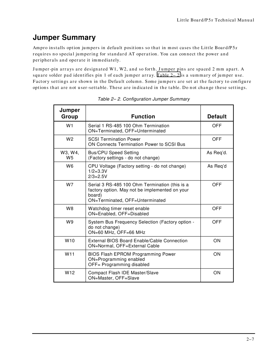
Ampro installs option jumpers in default positions so that in most cases the Little Board/P5x requires no special jumpering for standard AT operation. You can connect the power and peripherals and operate it immediately.
Table 2– 2. Configuration Jumper Summary
Jumper |
|
|
Group | Function | Default |
|
|
|
W1 | Serial 1 | OFF |
| ON=Terminated, OFF=Unterminated |
|
W2 | SCSI Termination Power | OFF |
| ON Connects Termination Power to SCSI Bus |
|
W3, W4, | Bus/CPU Speed Setting | As Req’d. |
W5 | (Factory settings - do not change) |
|
W6 | CPU Voltage (Factory setting - do not change) | As Req’d |
| 1/2=3.3V |
|
| 2/3=2.5V |
|
W7 | Serial 3 | OFF |
| factory option. May not be implemented on your |
|
| board) |
|
| ON=Terminated, OFF=Unterminated |
|
W8 | Watchdog timer reset enable | OFF |
| ON=Enabled, OFF=Disabled |
|
W9 | System Bus Frequency Selection (Factory option - | OFF |
| do not change) |
|
| ON=60 MHz, OFF=66 MHz |
|
W10 | External BIOS Board Enable/Cable Connection | ON |
| ON=Normal, OFF=External Cable |
|
W11 | BIOS Flash EPROM Programming Power | ON |
| ON=Programming enabled |
|
| OFF= Programming disabled |
|
W12 | Compact Flash IDE Master/Slave | ON |
| ON=Master, OFF=Slave |
|