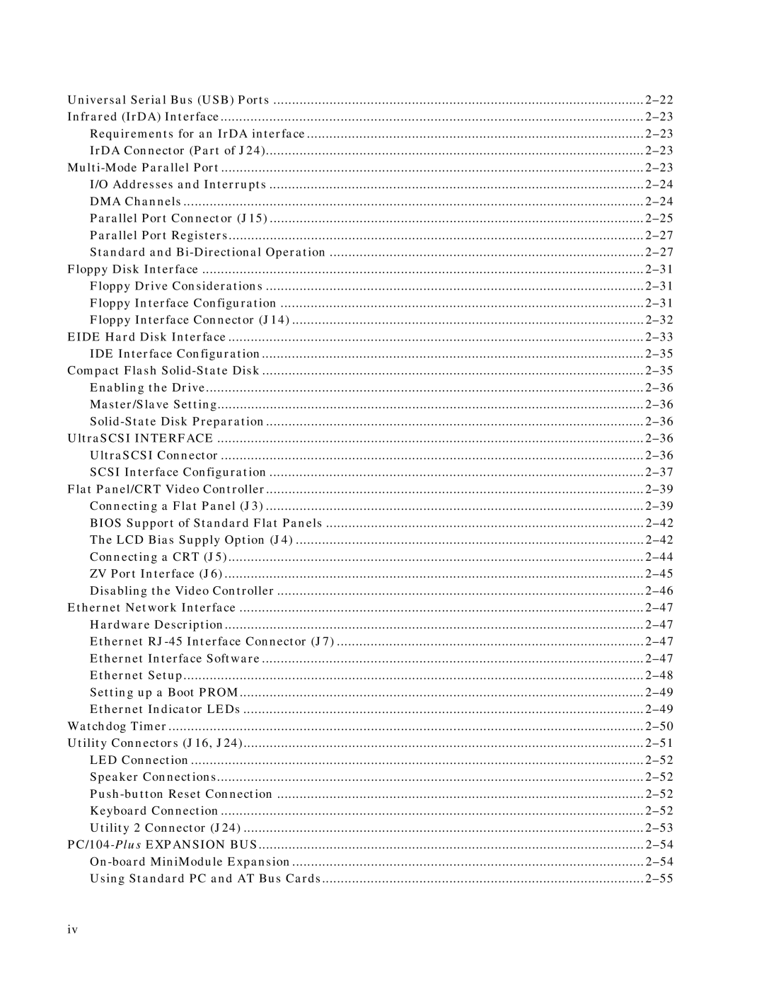
Universal Serial Bus (USB) Ports | |
Infrared (IrDA) Interface | |
Requirements for an IrDA interface | |
IrDA Connector (Part of J24) | |
I/O Addresses and Interrupts | |
DMA Channels | |
Parallel Port Connector (J15) | |
Parallel Port Registers | |
Standard and | |
Floppy Disk Interface | |
Floppy Drive Considerations | |
Floppy Interface Configuration | |
Floppy Interface Connector (J14) | |
EIDE Hard Disk Interface | |
IDE Interface Configuration | |
Compact Flash | |
Enabling the Drive | |
Master/Slave Setting | |
UltraSCSI INTERFACE | |
UltraSCSI Connector | |
SCSI Interface Configuration | |
Flat Panel/CRT Video Controller | |
Connecting a Flat Panel (J3) | |
BIOS Support of Standard Flat Panels | |
The LCD Bias Supply Option (J4) | |
Connecting a CRT (J5) | |
ZV Port Interface (J6) | |
Disabling the Video Controller | |
Ethernet Network Interface | |
Hardware Description | |
Ethernet | |
Ethernet Interface Software | |
Ethernet Setup | |
Setting up a Boot PROM | |
Ethernet Indicator LEDs | |
Watchdog Timer | |
Utility Connectors (J16, J24) | |
LED Connection | |
Speaker Connections | |
Keyboard Connection | |
Utility 2 Connector (J24) | |
Using Standard PC and AT Bus Cards |
iv
