Little Board/P5x Technical Manual
Please refer to the
Latch-Up Protection
The parallel port incorporates chip protection circuitry on some inputs, designed to minimize the possibility of CMOS “latch up” due to a printer or other peripheral being powered up while the Little Board/P5x is turned off.
Parallel Port Registers
The
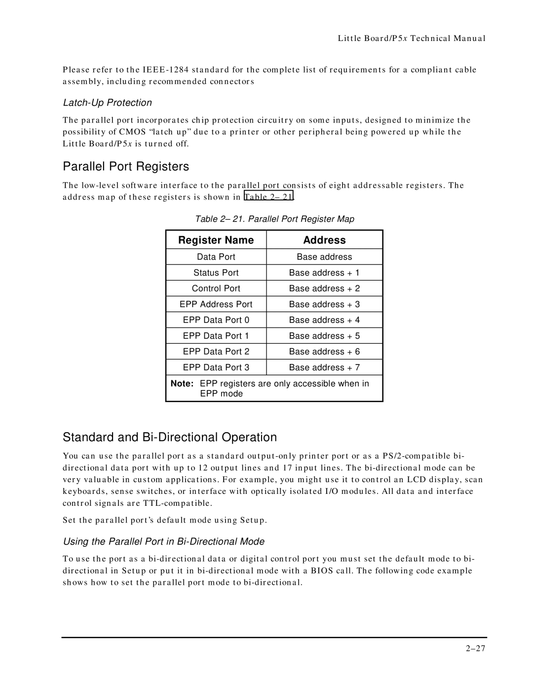
Table 2– 21. Parallel Port Register Map
Register Name | Address |
Data Port | Base address |
|
|
Status Port | Base address + 1 |
|
|
Control Port | Base address + 2 |
|
|
EPP Address Port | Base address + 3 |
|
|
EPP Data Port 0 | Base address + 4 |
|
|
EPP Data Port 1 | Base address + 5 |
|
|
EPP Data Port 2 | Base address + 6 |
|
|
EPP Data Port 3 | Base address + 7 |
|
|
Note: EPP registers are only accessible when in
EPP mode
Standard and Bi-Directional Operation
You can use the parallel port as a standard
Set the parallel port’s default mode using Setup.
Using the Parallel Port in Bi-Directional Mode
To use the port as a