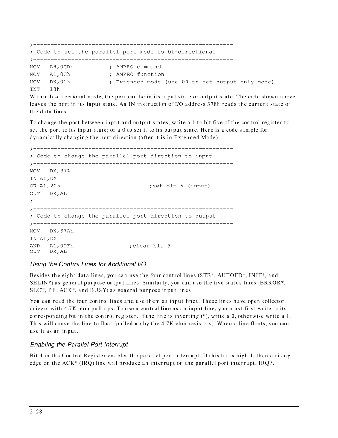
; Code to set the parallel port mode to
|
|
|
| ||
MOV | AH,0CDh | ; AMPRO | command |
| |
MOV | AL,0Ch | ; | AMPRO | function | |
MOV | BX,01h | ; | Extended mode | (use 00 to set | |
INT | 13h |
|
|
|
|
Within
To change the port between input and output states, write a 1 to bit five of the control register to set the port to its input state; or a 0 to set it to its output state. Here is a code sample for dynamically changing the port direction (after it is in Extended Mode).
; Code to change the parallel port direction to input
| ||
MOV | DX,37A |
|
IN AL,DX |
| |
OR AL,20h | ;set bit 5 (input) | |
OUT | DX,AL |
|
; |
|
|
; Code to change the parallel port direction to output
| ||
MOV | DX,37Ah |
|
IN AL,DX |
| |
AND | AL,0DFh | ;clear bit 5 |
OUT | DX,AL |
|
Using the Control Lines for Additional I/O
Besides the eight data lines, you can use the four control lines (STB*, AUTOFD*, INIT*, and SELIN*) as general purpose output lines. Similarly, you can use the five status lines (ERROR*, SLCT, PE, ACK*, and BUSY) as general purpose input lines.
You can read the four control lines and use them as input lines. These lines have open collector drivers with 4.7K ohm
Enabling the Parallel Port Interrupt
Bit 4 in the Control Register enables the parallel port interrupt. If this bit is high 1, then a rising edge on the ACK* (IRQ) line will produce an interrupt on the parallel port interrupt, IRQ7.
