PC/104-PlusEXPANSION BUS
The PC/104-Plusexpansion bus appears on three header connectors, P1, P2, and J21. P1 is a 64-pin female dual-row header. P2 is a 40-pin female dual-row header, and J21 is a 120-pin 2mm female quad-row header (4 x 30). The PC-bus subset of the PC/104-Plusexpansion bus connects to P1. The AT expansion bus signals connect to P2. The layout of signals on P1 and P2 is compliant with the PC/104 bus specification, and make up the ISA bus portion of the PC/104-Plusbus. An implementation of the PCI bus appears on J21.
PC/104-compatible expansion modules can be installed on the Little Board/P5x expansion bus. The buffered output signals to the expansion bus are standard TTL level signals. All inputs to the Little Board/P5x operate at TTL levels and present a typical CMOS load to the expansion bus.
On-board MiniModule Expansion
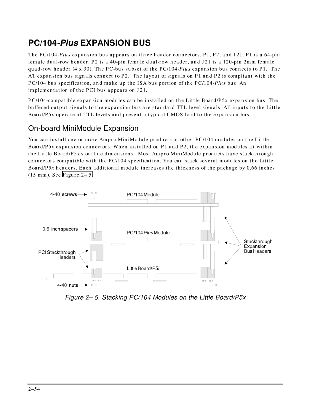
You can install one or more Ampro MiniModule products or other PC/104 modules on the Little Board/P5x expansion connectors. When installed on P1 and P2, the expansion modules fit within the Little Board/P5x’s outline dimensions. Most Ampro MiniModule products have stackthrough connectors compatible with the PC/104 specification. You can stack several modules on the Little Board/P5x headers. Each additional module increases the thickness of the package by 0.66 inches (15 mm). See Figure 2– 5.
Figure 2– 5. Stacking PC/104 Modules on the Little Board/P5x