200 MMX | 15.3 | 41.5 | 55.4 | 59.1 | ||
|
|
|
|
| ||
233 MMX | 10.8 | 39.2 | 54.2 | 58.2 | ||
|
|
|
|
|
| |
133 | VRT | 55.0 | 69.4 | 77.0 | 79.0 | |
|
|
|
|
|
| |
166 | Tillamook | 63.3 | 73.2 | 79.2 | 80.7 | |
|
|
|
|
|
| |
266 | Tillamook | 51.3 | 67.5 | 76.0 | 78.3 | |
|
|
|
|
| ||
Thermal Resistance of |
|
|
|
| ||
a Typical .65” Heat Sink | 7.5 | 3.9 | 2.0 | 1.5 | ||
and Fan/Heatsink | ||||||
|
|
|
| |||
Combination |
|
|
|
| ||
|
|
|
|
|
| |
Thermal Sensor
A thermal sensor is attached to the board under the Pentium CPU. It senses when the CPU temperature exceeds its upper temperature threshold. Running the CPU at a temperature higher than this can damage the CPU chip and should be avoided.
When triggered, the temperature sensor signals the BIOS to reduce the CPU clock speed. This speed reduction remains in effect until the processor has cooled to the lower sensor limit.
Fan Switch
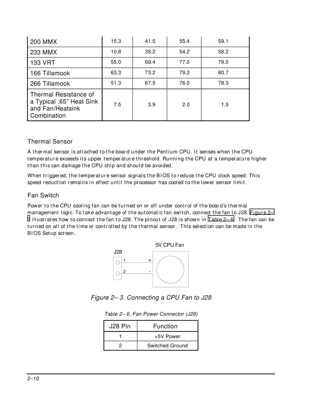
Power to the CPU cooling fan can be turned on or off under control of the board’s thermal management logic. To take advantage of the automatic fan switch, connect the fan to J28. Figure 2– 3 illustrates how to connect the fan to J28. The pinout of J28 is shown in Table 2– 6. The fan can be turned on all of the time or controlled by the thermal sensor. This selection can be made in the BIOS Setup screen.
5V CPU Fan
J28
1+
2-
Figure 2– 3. Connecting a CPU Fan to J28
Table 2– 6. Fan Power Connector (J28)
J28 Pin | Function |
1+5V Power
2Switched Ground