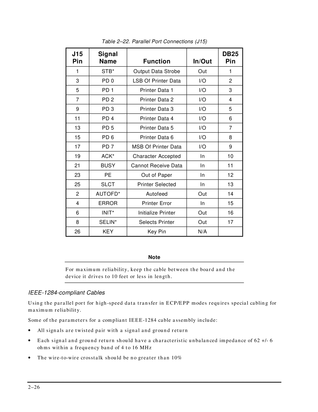
Table
J15 | Signal |
|
| DB25 |
Pin | Name | Function | In/Out | Pin |
|
|
|
|
|
1 | STB* | Output Data Strobe | Out | 1 |
|
|
|
|
|
3 | PD 0 | LSB Of Printer Data | I/O | 2 |
|
|
|
|
|
5 | PD 1 | Printer Data 1 | I/O | 3 |
|
|
|
|
|
7 | PD 2 | Printer Data 2 | I/O | 4 |
|
|
|
|
|
9 | PD 3 | Printer Data 3 | I/O | 5 |
|
|
|
|
|
11 | PD 4 | Printer Data 4 | I/O | 6 |
|
|
|
|
|
13 | PD 5 | Printer Data 5 | I/O | 7 |
|
|
|
|
|
15 | PD 6 | Printer Data 6 | I/O | 8 |
|
|
|
|
|
17 | PD 7 | MSB Of Printer Data | I/O | 9 |
|
|
|
|
|
19 | ACK* | Character Accepted | In | 10 |
|
|
|
|
|
21 | BUSY | Cannot Receive Data | In | 11 |
|
|
|
|
|
23 | PE | Out of Paper | In | 12 |
|
|
|
|
|
25 | SLCT | Printer Selected | In | 13 |
|
|
|
|
|
2 | AUTOFD* | Autofeed | Out | 14 |
|
|
|
|
|
4 | ERROR | Printer Error | In | 15 |
|
|
|
|
|
6 | INIT* | Initialize Printer | Out | 16 |
|
|
|
|
|
8 | SELIN* | Selects Printer | Out | 17 |
|
|
|
|
|
26 | KEY | Key Pin | N/A |
|
|
|
|
|
|
Note
For maximum reliability, keep the cable between the board and the device it drives to 10 feet or less in length.
IEEE-1284-compliant Cables
Using the parallel port for
Some of the parameters for a compliant
•All signals are twisted pair with a signal and ground return
•Each signal and ground return should have a characteristic unbalanced impedance of 62 +/- 6 ohms within a frequency band of 4 to 16 MHz
•The