Little Board/P5x Technical Manual
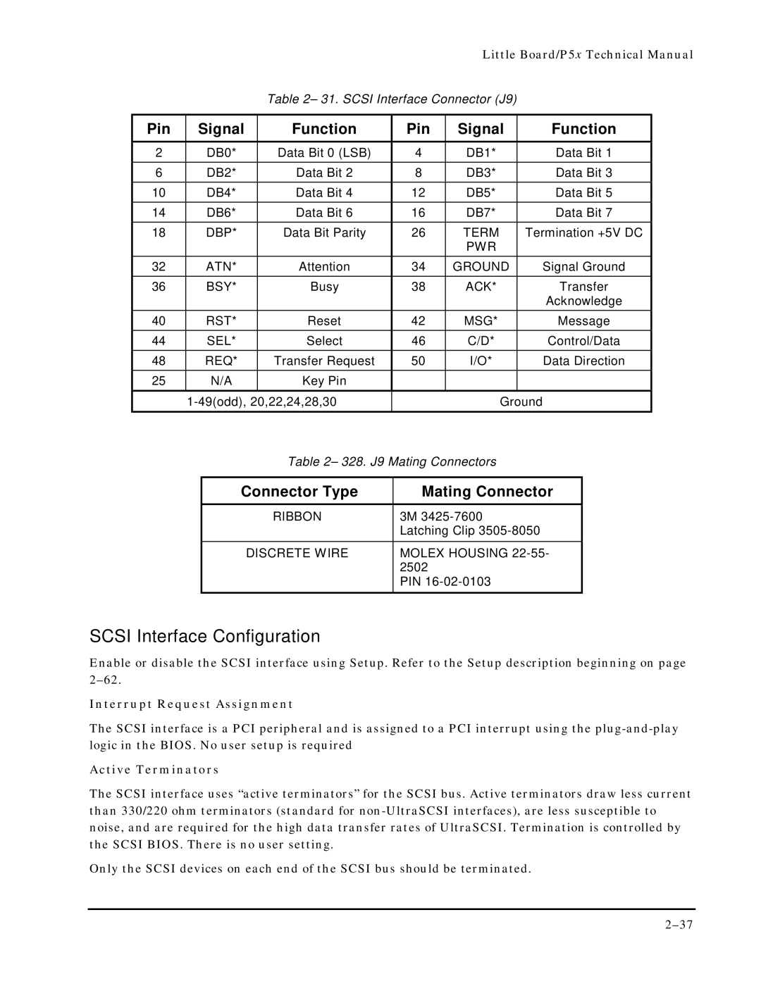
Table 2– 31. SCSI Interface Connector (J9)
Pin | Signal |
| Function |
| Pin | Signal | Function | ||
2 |
| DB0* |
| Data Bit 0 (LSB) | 4 | DB1* | Data Bit 1 | ||
6 |
| DB2* |
| Data Bit 2 | 8 | DB3* | Data Bit 3 | ||
10 |
| DB4* |
| Data Bit 4 | 12 | DB5* | Data Bit 5 | ||
14 |
| DB6* |
| Data Bit 6 | 16 | DB7* | Data Bit 7 | ||
18 |
| DBP* |
| Data Bit Parity | 26 | TERM | Termination +5V DC | ||
|
|
|
|
|
|
| PWR |
|
|
32 |
| ATN* |
| Attention | 34 | GROUND | Signal Ground | ||
36 |
| BSY* |
| Busy | 38 | ACK* | Transfer | ||
|
|
|
|
|
|
|
| Acknowledge | |
40 |
| RST* |
| Reset | 42 | MSG* | Message | ||
44 |
| SEL* |
| Select | 46 | C/D* | Control/Data | ||
48 |
| REQ* |
| Transfer Request | 50 | I/O* | Data Direction | ||
25 |
| N/A |
| Key Pin |
|
|
|
|
|
|
|
| Ground | ||||||
|
|
|
| Table 2– 328. J9 Mating Connectors |
|
| |||
|
|
|
|
|
| ||||
|
| Connector Type |
| Mating Connector |
| ||||
|
|
|
| RIBBON |
| 3M |
|
| |
|
|
|
|
|
| Latching Clip |
| ||
|
|
| DISCRETE WIRE |
| MOLEX HOUSING |
| |||
|
|
|
|
|
| 2502 |
|
|
|
|
|
|
|
|
| PIN |
|
| |
SCSI Interface Configuration
Enable or disable the SCSI interface using Setup. Refer to the Setup description beginning on page
Interrupt Request Assignment
The SCSI interface is a PCI peripheral and is assigned to a PCI interrupt using the
Active Terminators
The SCSI interface uses “active terminators” for the SCSI bus. Active terminators draw less current than 330/220 ohm terminators (standard for
Only the SCSI devices on each end of the SCSI bus should be terminated.