Little Board/P5x Technical Manual
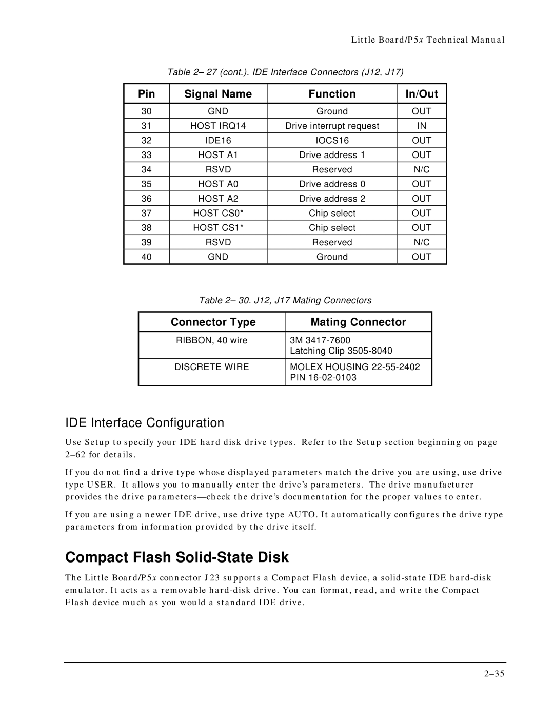
Table 2– 27 (cont.). IDE Interface Connectors (J12, J17)
| Pin | Signal Name |
| Function | In/Out | |
30 | GND |
| Ground | OUT | ||
31 | HOST IRQ14 |
| Drive interrupt request | IN | ||
32 | IDE16 |
| IOCS16 | OUT | ||
33 | HOST A1 |
| Drive address 1 | OUT | ||
34 | RSVD |
| Reserved | N/C | ||
35 | HOST A0 |
| Drive address 0 | OUT | ||
36 | HOST A2 |
| Drive address 2 | OUT | ||
37 | HOST CS0* |
| Chip select | OUT | ||
38 | HOST CS1* |
| Chip select | OUT | ||
39 | RSVD |
| Reserved | N/C | ||
40 | GND |
| Ground | OUT | ||
|
| Table 2– 30. J12, J17 Mating Connectors |
|
| ||
|
|
|
|
|
| |
|
| Connector Type |
| Mating Connector |
| |
|
| RIBBON, 40 wire |
| 3M |
|
|
|
|
|
| Latching Clip |
|
|
|
| DISCRETE WIRE |
| MOLEX HOUSING |
| |
|
|
|
| PIN |
|
|
IDE Interface Configuration
Use Setup to specify your IDE hard disk drive types. Refer to the Setup section beginning on page
If you do not find a drive type whose displayed parameters match the drive you are using, use drive type USER. It allows you to manually enter the drive’s parameters. The drive manufacturer provides the drive
If you are using a newer IDE drive, use drive type AUTO. It automatically configures the drive type parameters from information provided by the drive itself.
Compact Flash Solid-State Disk
The Little Board/P5x connector J23 supports a Compact Flash device, a