Floppy Interface Connector (J14)
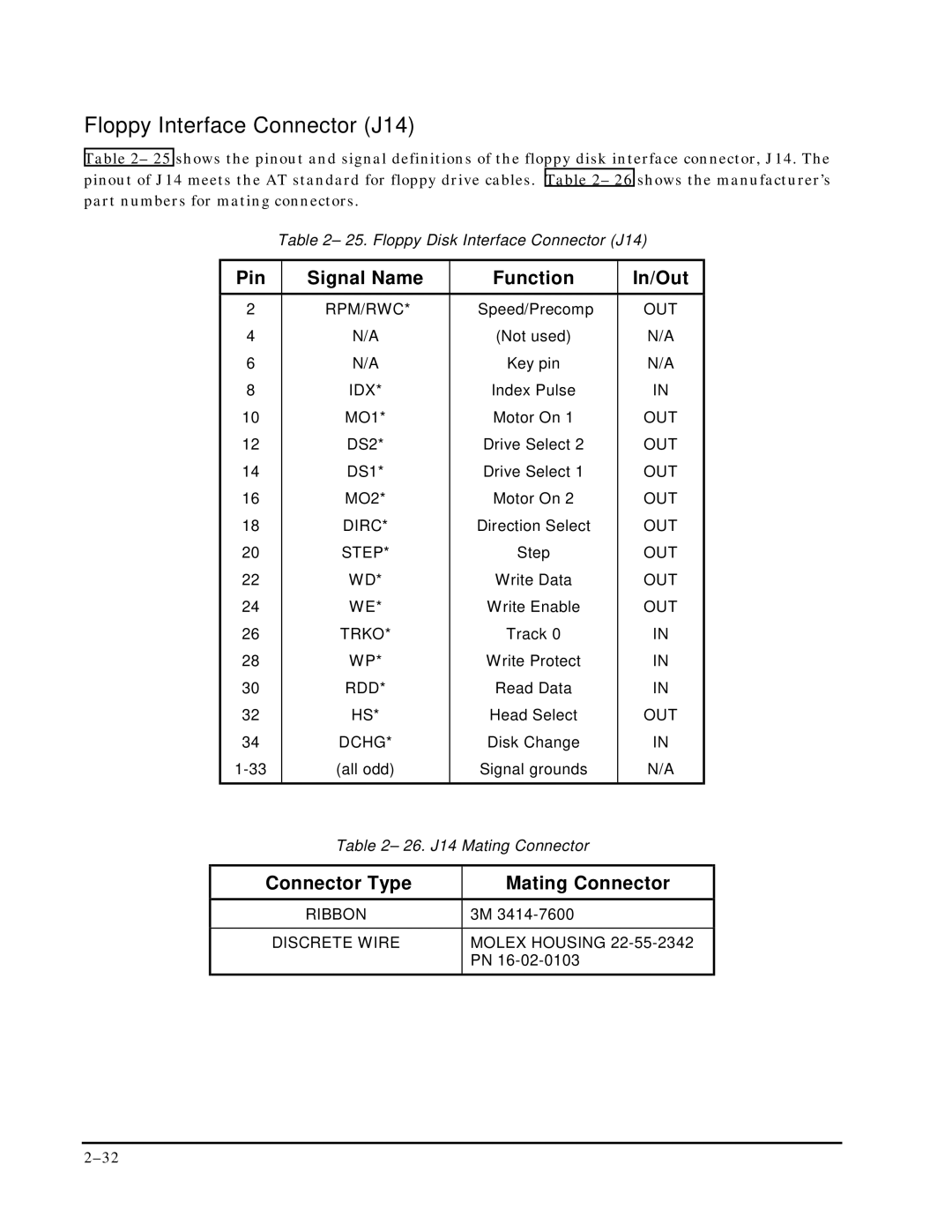
Table 2– 25 shows the pinout and signal definitions of the floppy disk interface connector, J14. The pinout of J14 meets the AT standard for floppy drive cables. Table 2– 26 shows the manufacturer’s part numbers for mating connectors.
Table 2– 25. Floppy Disk Interface Connector (J14)
| Pin |
| Signal Name |
| Function | In/Out |
|
|
|
|
|
|
|
|
|
| 2 |
| RPM/RWC* |
| Speed/Precomp | OUT |
|
| 4 |
| N/A |
| (Not used) | N/A |
|
| 6 |
| N/A |
| Key pin | N/A |
|
| 8 |
| IDX* |
| Index Pulse | IN |
|
| 10 |
| MO1* |
| Motor On 1 | OUT |
|
| 12 |
| DS2* |
| Drive Select 2 | OUT |
|
| 14 |
| DS1* |
| Drive Select 1 | OUT |
|
| 16 |
| MO2* |
| Motor On 2 | OUT |
|
| 18 |
| DIRC* |
| Direction Select | OUT |
|
| 20 |
| STEP* |
| Step | OUT |
|
| 22 |
| WD* |
| Write Data | OUT |
|
| 24 |
| WE* |
| Write Enable | OUT |
|
| 26 |
| TRKO* |
| Track 0 | IN |
|
| 28 |
| WP* |
| Write Protect | IN |
|
| 30 |
| RDD* |
| Read Data | IN |
|
| 32 |
| HS* |
| Head Select | OUT |
|
| 34 |
| DCHG* |
| Disk Change | IN |
|
|
| (all odd) |
| Signal grounds | N/A |
| |
|
|
|
|
|
|
|
|
|
|
| Table 2– 26. J14 Mating Connector |
|
| ||
|
|
|
|
| |||
| Connector Type |
| Mating Connector |
| |||
|
|
|
|
|
|
|
|
|
|
| RIBBON |
| 3M |
|
|
|
|
|
|
|
| ||
|
| DISCRETE WIRE |
| MOLEX HOUSING |
| ||
|
|
|
|
| PN |
|
|