variety of embedded applications requiring low-to-medium-speed data transfer between two or more systems.
Note
When you configure Serial 1 for RS-485, you cannot use the port for
RS-232.
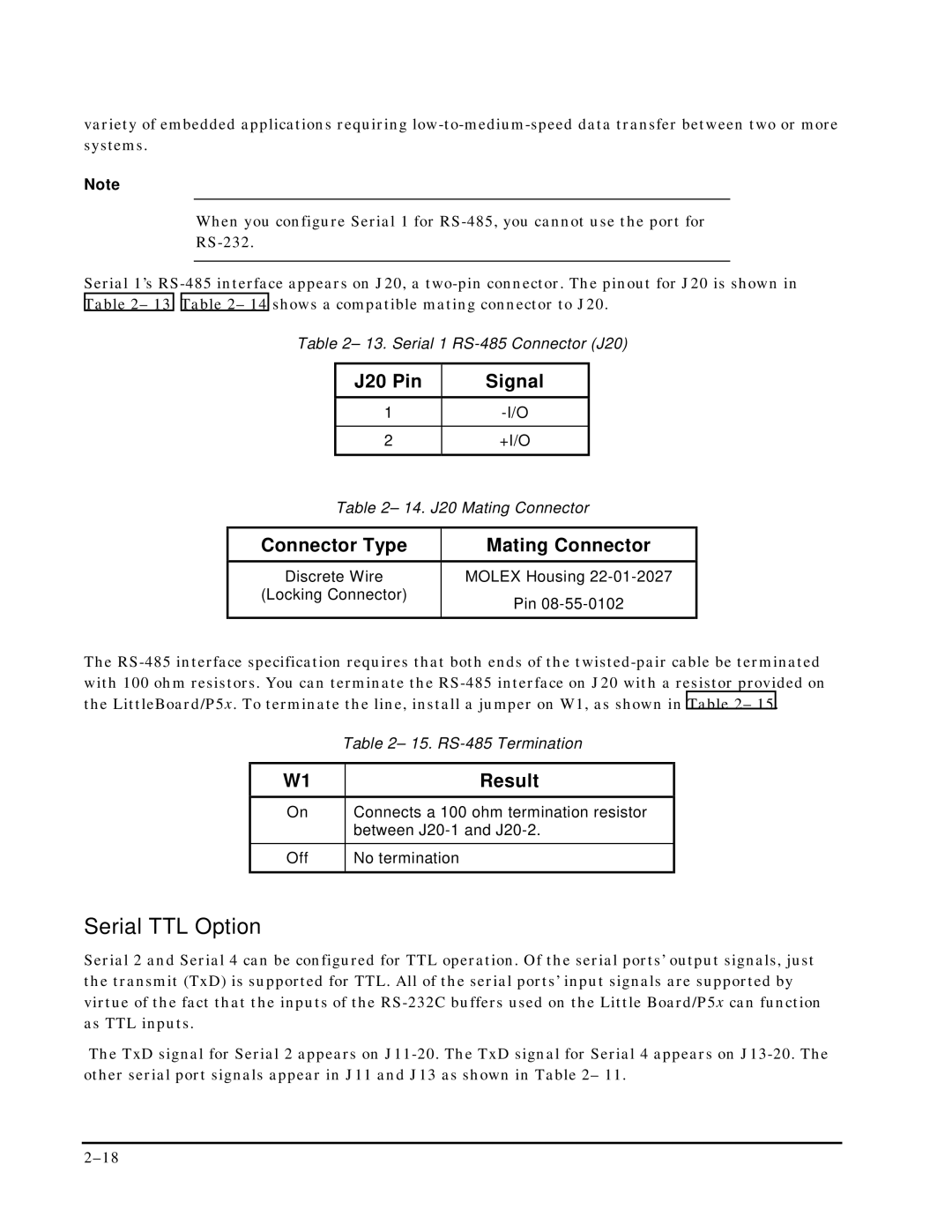
Serial 1’s RS-485 interface appears on J20, a two-pin connector. The pinout for J20 is shown in Table 2– 13. Table 2– 14 shows a compatible mating connector to J20.
Table 2– 13. Serial 1 RS-485 Connector (J20)
| J20 Pin | Signal | |
| | | |
| 1 | -I/O | |
| | | |
| 2 | +I/O | |
| | | |
| Table 2– 14. J20 Mating Connector |
| |
Connector Type | Mating Connector |
Discrete Wire | MOLEX Housing 22-01-2027 |
(Locking Connector) | Pin 08-55-0102 |
| |
| | | |
The RS-485 interface specification requires that both ends of the twisted-pair cable be terminated with 100 ohm resistors. You can terminate the RS-485 interface on J20 with a resistor provided on the LittleBoard/P5x. To terminate the line, install a jumper on W1, as shown in Table 2– 15.
| Table 2– 15. RS-485 Termination |
| | |
W1 | | Result |
On | | Connects a 100 ohm termination resistor |
| | between J20-1 and J20-2. |
Off | | No termination |
| | |
Serial TTL Option
Serial 2 and Serial 4 can be configured for TTL operation. Of the serial ports’ output signals, just the transmit (TxD) is supported for TTL. All of the serial ports’ input signals are supported by virtue of the fact that the inputs of the RS-232C buffers used on the Little Board/P5x can function as TTL inputs.
The TxD signal for Serial 2 appears on J11-20. The TxD signal for Serial 4 appears on J13-20. The other serial port signals appear in J11 and J13 as shown in Table 2– 11.