|
| Little Board/P5x Technical Manual | |
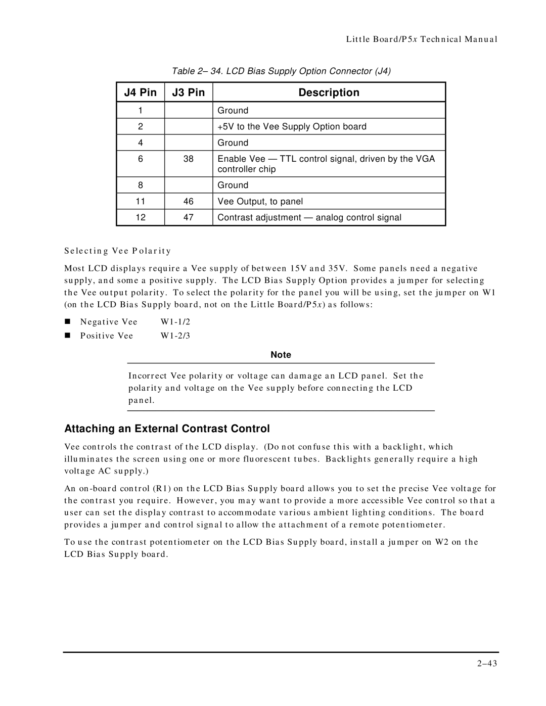
| Table 2– 34. LCD Bias Supply Option Connector (J4) | ||
|
|
|
|
J4 Pin | J3 Pin | Description |
|
1 |
| Ground |
|
|
|
|
|
2 |
| +5V to the Vee Supply Option board |
|
|
|
|
|
4 |
| Ground |
|
|
|
|
|
6 | 38 | Enable Vee — TTL control signal, driven by the VGA |
|
|
| controller chip |
|
8 |
| Ground |
|
|
|
|
|
11 | 46 | Vee Output, to panel |
|
|
|
|
|
12 | 47 | Contrast adjustment — analog control signal |
|
|
|
|
|
Selecting Vee Polarity
Most LCD displays require a Vee supply of between 15V and 35V. Some panels need a negative supply, and some a positive supply. The LCD Bias Supply Option provides a jumper for selecting the Vee output polarity. To select the polarity for the panel you will be using, set the jumper on W1 (on the LCD Bias Supply board, not on the Little Board/P5x) as follows:
! | Negative Vee | |
! | Positive Vee |
Note
Incorrect Vee polarity or voltage can damage an LCD panel. Set the polarity and voltage on the Vee supply before connecting the LCD panel.
Attaching an External Contrast Control
Vee controls the contrast of the LCD display. (Do not confuse this with a backlight, which illuminates the screen using one or more fluorescent tubes. Backlights generally require a high voltage AC supply.)
An
To use the contrast potentiometer on the LCD Bias Supply board, install a jumper on W2 on the LCD Bias Supply board.