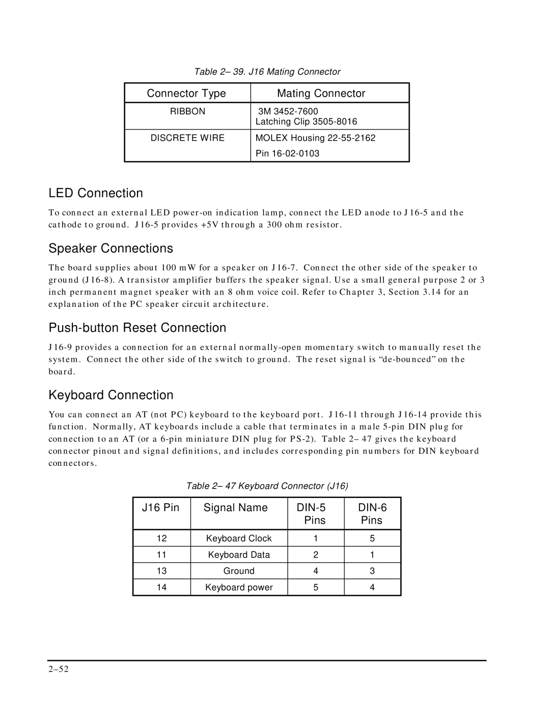
Table 2– 39. J16 Mating Connector
Connector Type | Mating Connector |
RIBBON | 3M 3452-7600 |
| Latching Clip 3505-8016 |
DISCRETE WIRE | MOLEX Housing 22-55-2162 |
| Pin 16-02-0103 |
| |
LED Connection
To connect an external LED power-on indication lamp, connect the LED anode to J16-5 and the cathode to ground. J16-5 provides +5V through a 300 ohm resistor.
Speaker Connections
The board supplies about 100 mW for a speaker on J16-7. Connect the other side of the speaker to ground (J16-8). A transistor amplifier buffers the speaker signal. Use a small general purpose 2 or 3 inch permanent magnet speaker with an 8 ohm voice coil. Refer to Chapter 3, Section 3.14 for an explanation of the PC speaker circuit architecture.
Push-button Reset Connection
J16-9 provides a connection for an external normally-open momentary switch to manually reset the system. Connect the other side of the switch to ground. The reset signal is “de-bounced” on the board.
Keyboard Connection
You can connect an AT (not PC) keyboard to the keyboard port. J16-11 through J16-14 provide this function. Normally, AT keyboards include a cable that terminates in a male 5-pin DIN plug for connection to an AT (or a 6-pin miniature DIN plug for PS-2). Table 2– 47 gives the keyboard connector pinout and signal definitions, and includes corresponding pin numbers for DIN keyboard connectors.
Table 2– 47 Keyboard Connector (J16)
J16 Pin | Signal Name | DIN-5 | DIN-6 |
| | Pins | Pins |
12 | Keyboard Clock | 1 | 5 |
| | | |
11 | Keyboard Data | 2 | 1 |
| | | |
13 | Ground | 4 | 3 |
| | | |
14 | Keyboard power | 5 | 4 |
| | | |