Manuals
/
Ampro Corporation
/
Computer Equipment
/
Computer Hardware
Ampro Corporation
P5X
manual
0800805
Models:
P5X
1
114
121
121
Download
121 pages
56 Kb
111
112
113
114
115
116
117
118
System Block Diagram
J6 Pin Signal
Jumper Group Function Default
Watchdog Timer
Ethernet Indicator LEDs
Connecting a Flat Panel J3
Dimension
Floppy Interface Configuration
Push-button Reset Connection
Ethernet Setup
Page 114
Image 114
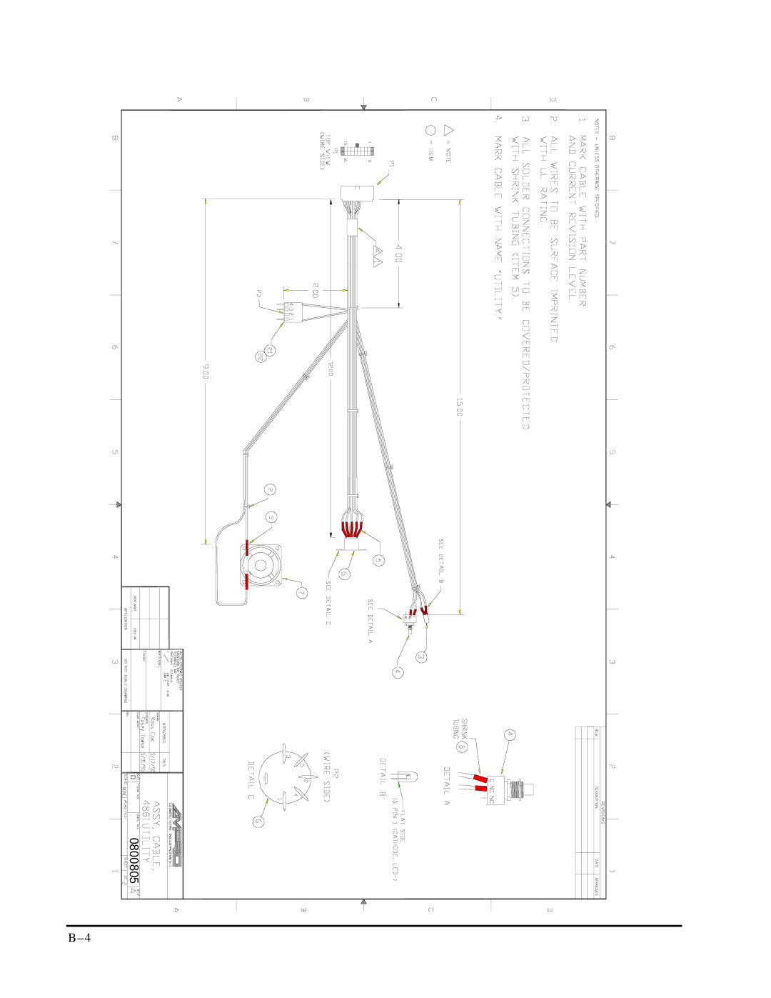
0800805
B–4
Page 113
Page 115
Page 114
Image 114
Page 113
Page 115
Contents
Little Board/P5x
Revision Reason for Change Date
Table of Contents
Page
Appendix a
Introduction
Technical Support
Product Feature Summary
Chapter
General Description
Enhanced Embedded-PC Bios
Compact Flash Disk
PCI UltraSCSI Interface
Enhanced Reliability
100 MB/s Ethernet LAN Interface
Software
Designing Little Board Systems
On-board MiniModule Expansion
Using Standard PC and AT Bus Cards
Little Board Development Platform And Quick Start Kit
Little Board/P5x Utility I/O Development Board
200 325 550 025 650 975 300 800 197
Connector Descriptions
J6 Pin Signal
Switch Descriptions S1 S4
J6 Power
Switch Name Description
System Block Diagram
Page
Overview
Mounting Dimensions
P2C P2D
Connector Summary
Connector Function Size Key Pin
Page
Connector and Jumper Locations
Jumper Group Function Default
Jumper Summary
Pin Signal Name Function
DC Power
Power Requirements
Connector Type Mating Connector
Powerfail NMI
Backup Battery
Cooling Requirements
Fan Switch
Thermal Sensor
J28 Pin Function
System Memory
Shadowing
Memory Address Function
Bios Recovery
Interrupt and DMA Channel Usage
Interrupt Function
Channel Function
Addresses and Interrupt Assignments
Battery-Backed Clock
Serial Ports
Port Address Interrupt
ROM-BIOS Installation of the Serial Ports
Serial Port Connectors J11, J13
RS-485 Option
DB9
J20 Pin Signal
Serial TTL Option
Ampro Custom Serial Features
Serial Console Features
Hex Command
Using a Standard PC Keyboard
Function Substitute Keys
Page
J24 Pin Signal Name Function
Universal Serial Bus USB Ports
Infrared IrDA Interface
IrDA Connector Part of J24
Signal J24 Pin Name Function
Multi-Mode Parallel Port
Addresses and Interrupts
DMA Channels
Selection Address Interrupt
Parallel Port Connector J15
J15 Signal DB25 Pin Name Function In/Out
IEEE-1284-compliant Cables
Parallel Port Registers
Standard and Bi-Directional Operation
Register Name Address
Using the Control Lines for Additional I/O
DB25F
Signal Name Full Name Description
Floppy Drive Considerations
Floppy Interface Configuration
Floppy Disk Interface
Capacity Drive Size Tracks Data Rate
Floppy Interface Connector J14
Pin Signal Name Function In/Out
Eide Hard Disk Interface
Pin Signal Name Function In/Out J12, J17
IDE Interface Configuration
Compact Flash Solid-State Disk
UltraSCSI Interface
Master/Slave Setting
UltraSCSI Connector
Enabling the Drive
Scsi Interface Configuration
Pin Signal Function
Scsi ID
Connecting a Flat Panel J3
Name Connector Pins/Type Description
Flat Panel/CRT Video Controller
Signal Pin Name Description
Signal Pin Name Description
Power Sequencing
Bios Support of Standard Flat Panels
Advanced Power Management
LCD Bias Supply Option J4
J4 Pin J3 Pin Description
Attaching an External Contrast Control
Connecting a CRT J5
Example
Pin Signal Name DB-15
ZV Port Interface J6
Disabling the Video Controller
J6 Pin Name Function
Hardware Description
Ethernet RJ-45 Interface Connector J7
Ethernet Network Interface
Ethernet Interface Software
Ethernet Setup
Network Operating Systems
Network OS Drivers
Setting up a Boot Prom
Ethernet Indicator LEDs
Color Designation Function
Watchdog Timer
15h
Utility Connectors J16, J24
LED Connection
Push-button Reset Connection
J16 Pin Signal Name DIN-5 DIN-6 Pins
Speaker Connections
Utility 2 Connector J24
PC/104-PlusEXPANSION BUS
Expansion Bus Connector Pinouts
50. PC/104 Expansion Bus Connector, P1 A1-A32
Signal Pin Name Function In/Out
52. PC/104 Expansion Bus Connector, P2 C0-C19
53. PC/104 Expansion Bus Connector, P2 D0-D19
PCI Bus P21 Notes
Page
Setup
Setup Help
Menu Name Functions
Menu Name Functions
Setup 1 Main Menu
Setup 1 Main Menu
Setup 2 Standard Cmos Setup
ESC
Eide Hard Disk Drives
Drive Selection
Video
Error Halt
Floppy Drives
Dram Memory
Setup 3 Bios Features Setup
Dram 64MB
Serial Console Operation During Setup
Page
Setup 4 Chipset Features Setup
Setup 4 Chipset Features Setup
Page
Setup 5 Power Management Setup
IRQ
Page
Setup 6 PCI Configuration Setup
ISA
Setup 7 Integrated Peripherals Setup
Integrated Peripherals Setup
Page
Page
Little Board/P5x Specifications
CPU/Motherboard
Embedded-PC System Enhancements
On-board Peripherals
Page
Mechanical and Environmental Specifications
Support Software
DOS Prompt Maximum CPU Speed
Amps / Watts
CRT LCD
Supported CRT Video Modes-Standard VGA
CRT Support for Standard Video Modes
CRT
CRT Support for Extended Resolution Modes
Shock and Vibration Testing
Ampro Product Reliability Testing
Regulatory testing
Wide-range temperature testing
Page
Contacts
EPP and ECP Operation
Page
Cables
Page
Little Board/P5x Technical Manual
0800805
0800805
Page
0800575 a
Page
Index
Expansion bus, 1-2 Expansion bus
Top
Page
Image
Contents