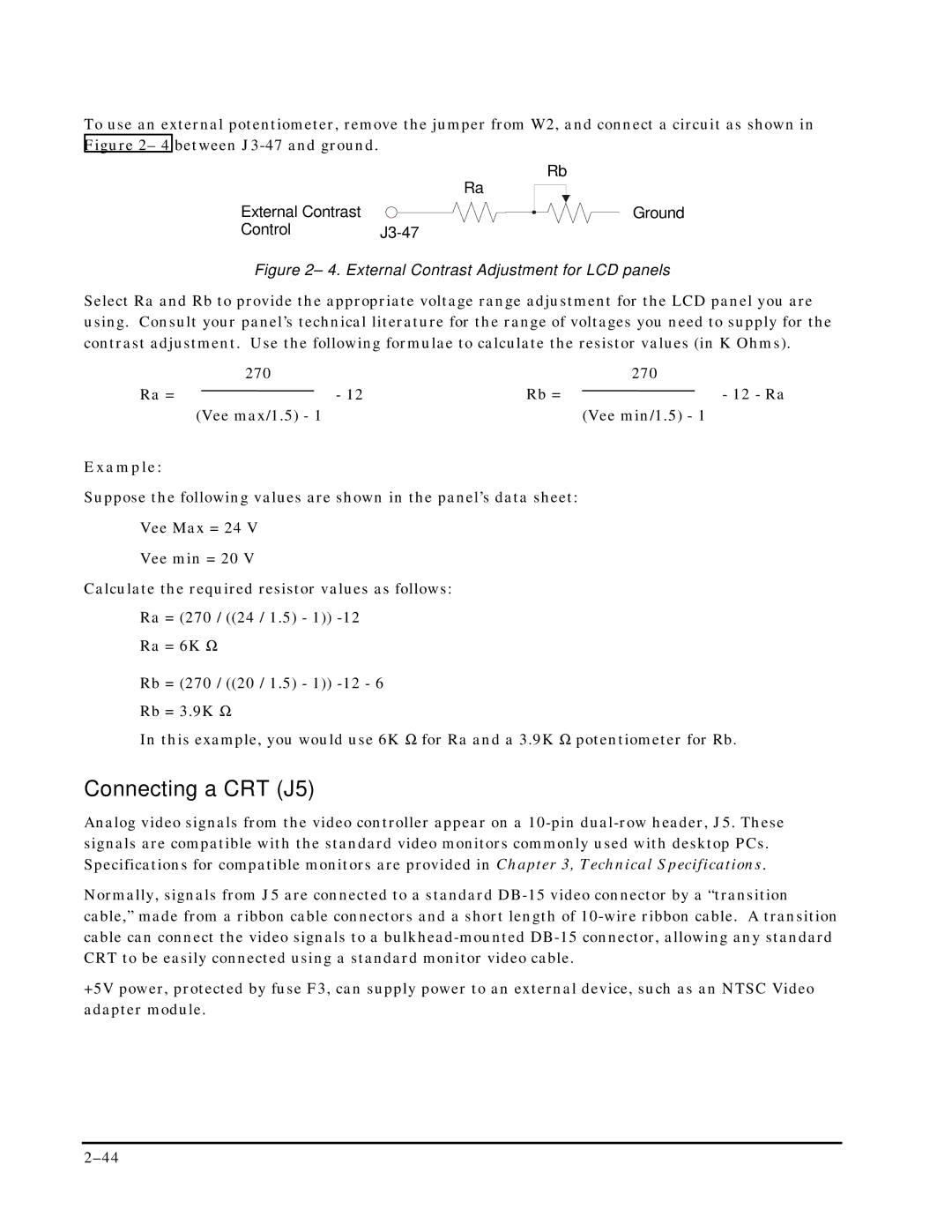
To use an external potentiometer, remove the jumper from W2, and connect a circuit as shown in Figure 2– 4 between
Ra
External Contrast
ControlJ3-47
Rb
Ground
Figure 2– 4. External Contrast Adjustment for LCD panels
Select Ra and Rb to provide the appropriate voltage range adjustment for the LCD panel you are using. Consult your panel’s technical literature for the range of voltages you need to supply for the contrast adjustment. Use the following formulae to calculate the resistor values (in K Ohms).
| 270 |
| 270 |
Ra = | - 12 | Rb = | - 12 - Ra |
| (Vee max/1.5) - 1 |
| (Vee min/1.5) - 1 |
Example:
Suppose the following values are shown in the panel’s data sheet:
Vee Max = 24 V
Vee min = 20 V
Calculate the required resistor values as follows:
Ra = (270 / ((24 / 1.5) - 1))
Ra = 6K Ω
Rb = (270 / ((20 / 1.5) - 1))
In this example, you would use 6K Ω for Ra and a 3.9K Ω potentiometer for Rb.
Connecting a CRT (J5)
Analog video signals from the video controller appear on a
Normally, signals from J5 are connected to a standard
+5V power, protected by fuse F3, can supply power to an external device, such as an NTSC Video adapter module.
