Little Board/P5x Technical Manual
connector, J10. This will supply +12V to the ISA and PCI portions of the PC/104 expansion busses. Similarly, you can connect
If a PCI expansion card requiring 3.3V is installed, that voltage can be connected to
Switching Power Supplies
If you use a switching power supply, be sure it regulates properly with the load your system draws. Some switching power supplies do not regulate properly unless they are loaded to some minimum value. If this is the case with your supply, consult the manufacturer about additional loading, or use another supply or another type of power source (such as a linear supply, batteries, etc.). The minimum power for the Little Board/P5x appears in the power specifications in Chapter 1.
Powerfail NMI
The Little Board/P5x includes a circuit that can sense a power failure. If the +5V power supply falls below ~4.7 V, the powerfail logic produces a
When an NMI occurs, the BIOS detects the NMI and displays the message “Power Fail NMI” on the console. At this point you have two options via the keyboard. You can mask the NMI and continue (the PC architecture provides a mask bit for the
If you want your system to respond to the NMI, you can provide an NMI handler in your application, and patch the NMI interrupt vector address to point to your routine.
Backup Battery
Real-Time Clock Battery
The
Cooling Requirements
The Pentium CPU, DRAM module, video controller, and core logic chips draw most of the power and generate most of the heat. The board is designed to support various speed versions of the Pentium from 133 MHz to 266 MHz with 66 MHz clocks. Since CPU speeds offered by manufacturers are continuing to increase, contact your Ampro sales representative for the currently available speeds.
A heat sink or fan assembly is provided for the CPU. The fan gets its +5V power from J28. J28 power can be controlled by a CPU thermal sensor, as described below.
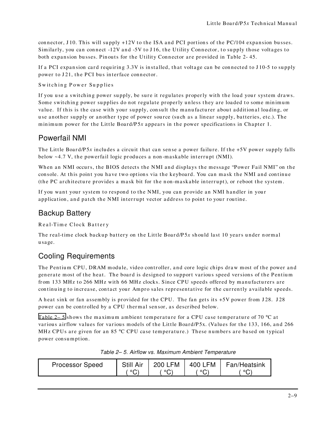
Table 2– 5 shows the maximum ambient temperature for a CPU case temperature of 70 ° C at various airflow values for various models of the Little Board/P5x. (Values for the 133, 166, and 266 MHz CPUs are given for an 85 ° C CPU case temperature.) These numbers are based on typical power consumption.
Table 2– 5. Airflow vs. Maximum Ambient Temperature
Processor Speed | Still Air | 200 LFM | 400 LFM | Fan/Heatsink |
| ( °C) | ( °C) | ( °C) | ( °C) |