Little Board/P5x Technical Manual
Floppy Disk Interface
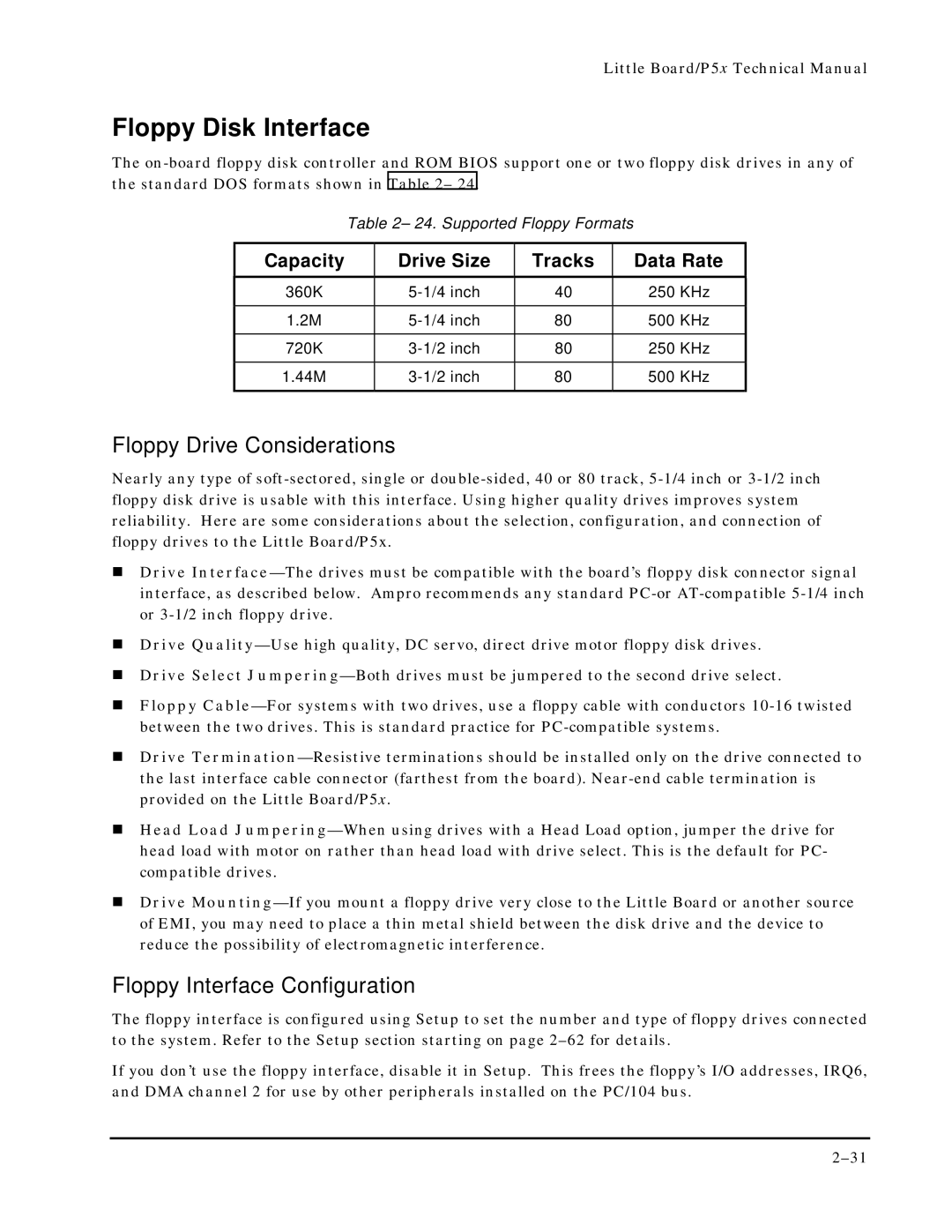
The on-board floppy disk controller and ROM BIOS support one or two floppy disk drives in any of the standard DOS formats shown in Table 2– 24.
Table 2– 24. Supported Floppy Formats
Capacity | Drive Size | Tracks | Data Rate |
360K | 5-1/4 inch | 40 | 250 KHz |
| | | |
1.2M | 5-1/4 inch | 80 | 500 KHz |
| | | |
720K | 3-1/2 inch | 80 | 250 KHz |
| | | |
1.44M | 3-1/2 inch | 80 | 500 KHz |
| | | |
Floppy Drive Considerations
Nearly any type of soft-sectored, single or double-sided, 40 or 80 track, 5-1/4 inch or 3-1/2 inch floppy disk drive is usable with this interface. Using higher quality drives improves system reliability. Here are some considerations about the selection, configuration, and connection of floppy drives to the Little Board/P5x.
!Drive Interface—The drives must be compatible with the board’s floppy disk connector signal interface, as described below. Ampro recommends any standard PC-or AT-compatible 5-1/4 inch or 3-1/2 inch floppy drive.
!Drive Quality—Use high quality, DC servo, direct drive motor floppy disk drives.
!Drive Select Jumpering—Both drives must be jumpered to the second drive select.
!Floppy Cable—For systems with two drives, use a floppy cable with conductors 10-16 twisted between the two drives. This is standard practice for PC-compatible systems.
!Drive Termination—Resistive terminations should be installed only on the drive connected to the last interface cable connector (farthest from the board). Near-end cable termination is provided on the Little Board/P5x.
!Head Load Jumpering—When using drives with a Head Load option, jumper the drive for head load with motor on rather than head load with drive select. This is the default for PC- compatible drives.
!Drive Mounting—If you mount a floppy drive very close to the Little Board or another source of EMI, you may need to place a thin metal shield between the disk drive and the device to reduce the possibility of electromagnetic interference.
Floppy Interface Configuration
The floppy interface is configured using Setup to set the number and type of floppy drives connected to the system. Refer to the Setup section starting on page 2–62 for details.
If you don’t use the floppy interface, disable it in Setup. This frees the floppy’s I/O addresses, IRQ6, and DMA channel 2 for use by other peripherals installed on the PC/104 bus.