Setup 7 — Integrated Peripherals Setup
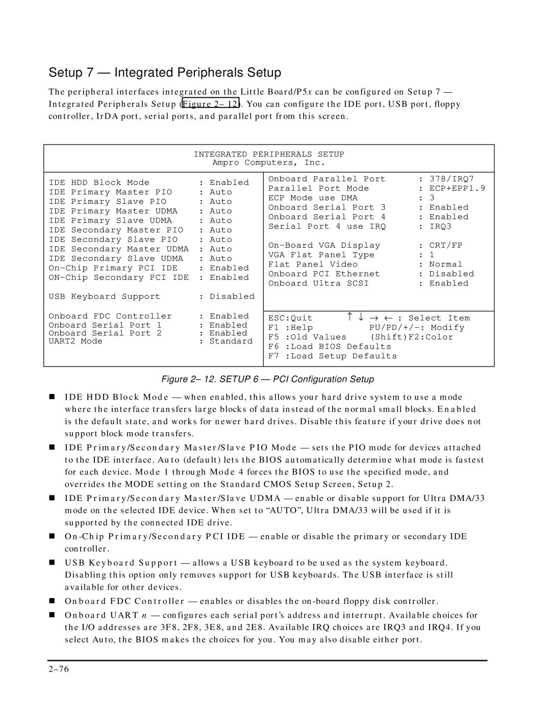
The peripheral interfaces integrated on the Little Board/P5x can be configured on Setup 7 — Integrated Peripherals Setup (Figure 2– 12). You can configure the IDE port, USB port, floppy controller, IrDA port, serial ports, and parallel port from this screen.
INTEGRATED PERIPHERALS SETUP
Ampro Computers, Inc.
IDE HDD Block Mode | : Enabled | Onboard Parallel Port | : 378/IRQ7 | |||
Parallel Port Mode |
| : ECP+EPP1.9 | ||||
IDE Primary Master PIO | : Auto |
| ||||
ECP Mode use DMA |
| : 3 | ||||
IDE Primary Slave PIO | : Auto |
| ||||
Onboard Serial Port 3 | : Enabled | |||||
IDE Primary Master UDMA | : Auto | |||||
Onboard Serial Port 4 | : Enabled | |||||
IDE Primary Slave UDMA | : Auto | |||||
Serial Port 4 use IRQ | : IRQ3 | |||||
IDE Secondary Master PIO | : Auto | |||||
|
|
|
| |||
IDE Secondary Slave PIO | : Auto | : CRT/FP | ||||
IDE Secondary Master UDMA | : Auto | |||||
VGA Flat Panel Type | : 1 | |||||
IDE Secondary Slave UDMA | : Auto | |||||
Flat Panel Video |
| : Normal | ||||
: Enabled |
| |||||
Onboard PCI Ethernet | : Disabled | |||||
: Enabled | ||||||
Onboard Ultra SCSI |
| : Enabled | ||||
|
|
| ||||
USB Keyboard Support | : Disabled |
|
|
|
| |
Onboard FDC Controller | : Enabled |
|
|
|
| |
ESC:Quit | ↑ ↓ | → ← | : Select Item | |||
Onboard Serial Port 1 | : Enabled | F1 :Help |
| |||
Onboard Serial Port 2 | : Enabled |
| ||||
F5 :Old Values |
| (Shift)F2:Color | ||||
UART2 Mode | : Standard |
| ||||
F6 :Load BIOS Defaults |
| |||||
|
|
| ||||
|
| F7 :Load Setup Defaults |
| |||
|
|
| ||||
Figure 2– 12. SETUP 6 — PCI Configuration Setup |
| |||||
!IDE HDD Block Mode — when enabled, this allows your hard drive system to use a mode where the interface transfers large blocks of data instead of the normal small blocks. Enabled is the default state, and works for newer hard drives. Disable this feature if your drive does not support block mode transfers.
!IDE Primary/Secondary Master/Slave PIO Mode — sets the PIO mode for devices attached to the IDE interface. Auto (default) lets the BIOS automatically determine what mode is fastest for each device. Mode 1 through Mode 4 forces the BIOS to use the specified mode, and overrides the MODE setting on the Standard CMOS Setup Screen, Setup 2.
!IDE Primary/Secondary Master/Slave UDMA — enable or disable support for Ultra DMA/33 mode on the selected IDE device. When set to “AUTO”, Ultra DMA/33 will be used if it is supported by the connected IDE drive.
!
!USB Keyboard Support — allows a USB keyboard to be used as the system keyboard. Disabling this option only removes support for USB keyboards. The USB interface is still available for other devices.
!Onboard FDC Controller — enables or disables the
!Onboard UART n — configures each serial port’s address and interrupt. Available choices for the I/O addresses are 3F8, 2F8, 3E8, and 2E8. Available IRQ choices are IRQ3 and IRQ4. If you select Auto, the BIOS makes the choices for you. You may also disable either port.