Configuring a Redundant Link
BNC:
An Example Configuration
According to the priority scheme described above, BNC will not be the active uplink if either an AUI or 10T connection exists. Due to this ordering, if BNC is selected, it is assumed that this medium is the only type available.
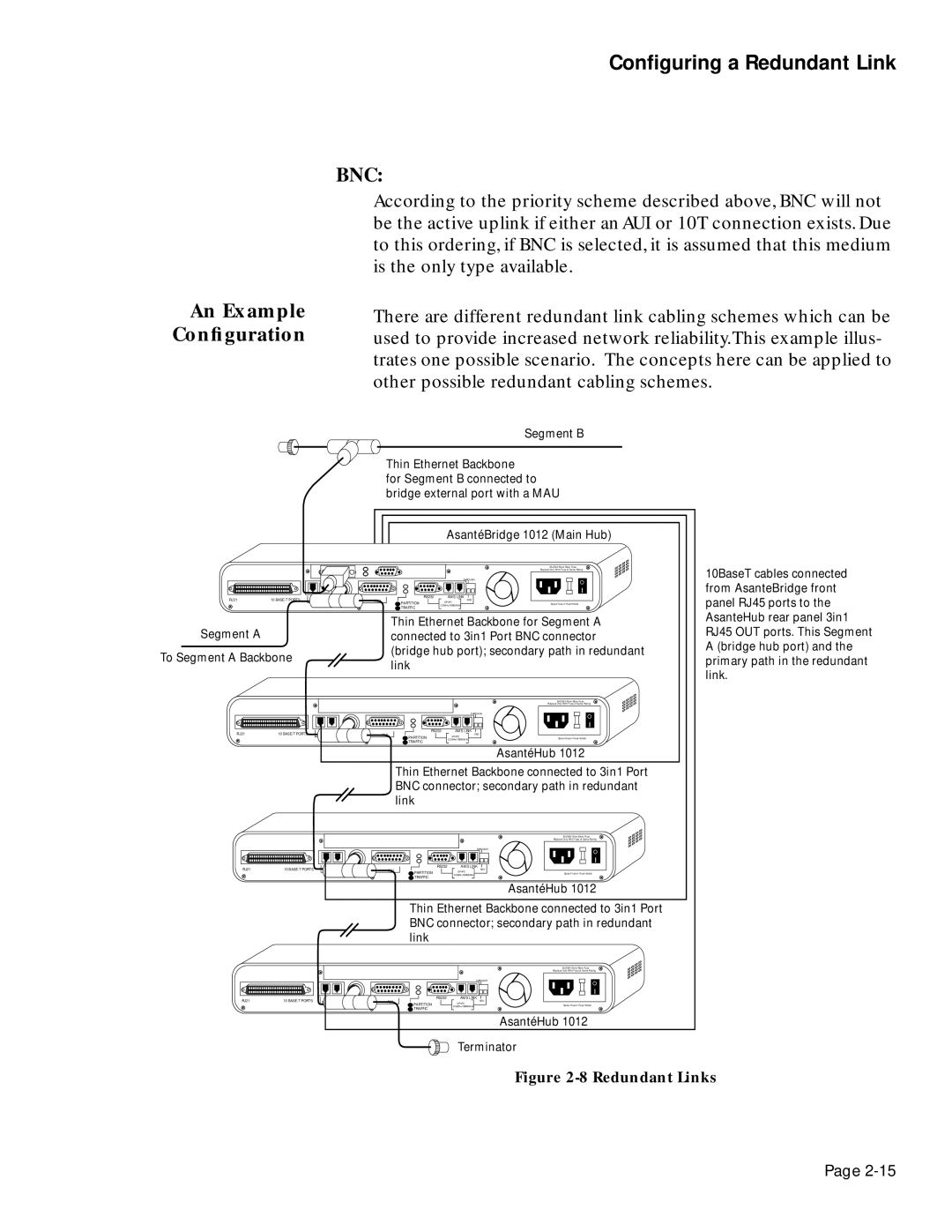
There are different redundant link cabling schemes which can be used to provide increased network reliability.This example illus- trates one possible scenario. The concepts here can be applied to other possible redundant cabling schemes.
Segment B
Thin Ethernet Backbone
for Segment B connected to bridge external port with a MAU
AsantéBridge 1012 (Main Hub)
2A/250V Slow Blow Fuse
Replace Only With Fuse of Same Rating
THROUGH |
RJ21 | 10 |
|
| RS232 | AMS LINK | END |
IN or OUT | BNC | AUI | UP=PC | |||
|
|
| PARTITION | DOWN=TERMINAL | Spare Fuse in Fuse Holder | |
|
|
| TRAFFIC |
| ||
|
|
|
|
|
|
Thin Ethernet Backbone for Segment A
Segment Aconnected to 3in1 Port BNC connector
10BaseT cables connected from AsanteBridge front panel RJ45 ports to the AsanteHub rear panel 3in1 RJ45 OUT ports. This Segment A (bridge hub port) and the
To Segment A Backbone
(bridge hub port); secondary path in redundant link
2A/250V Slow Blow Fuse
Replace Only With Fuse of Same Rating
primary path in the redundant link.
THROUGH |
RJ21 | 10 |
|
| RS232 | AMS LINK | END |
IN or OUT | BNC | AUI | UP=PC | |||
|
|
| PARTITION | DOWN=TERMINAL | Spare Fuse in Fuse Holder | |
|
|
| TRAFFIC |
| ||
|
|
|
|
|
|
AsantéHub 1012
Thin Ethernet Backbone connected to 3in1 Port BNC connector; secondary path in redundant link
2A/250V Slow Blow Fuse
Replace Only With Fuse of Same Rating
THROUGH |
RJ21 | 10 |
|
| RS232 | AMS LINK | END |
IN or OUT | BNC | AUI | UP=PC | |||
|
|
| PARTITION | DOWN=TERMINAL | Spare Fuse in Fuse Holder | |
|
|
|
| TRAFFIC |
|
|
AsantéHub 1012
Terminator
Figure 2-8 Redundant Links
Page