Using the 3in1 Port
Thin Ethernet Backbone
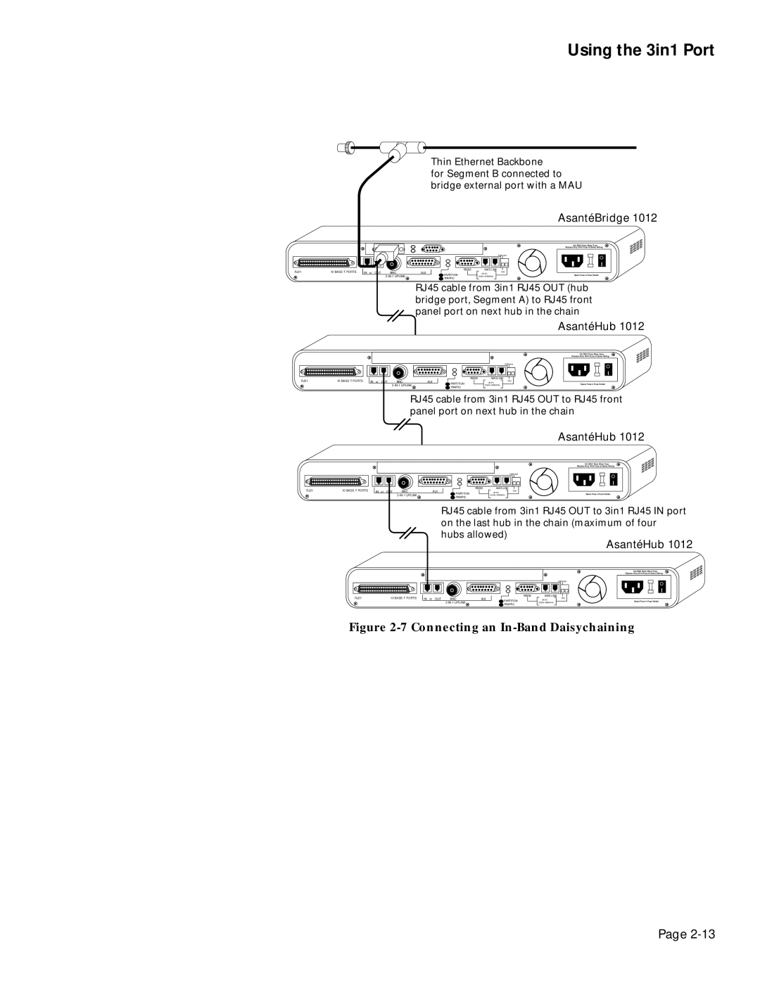
for Segment B connected to bridge external port with a MAU
RJ21 | 10 | IN or OUT | BNC | AUI |
|
|
|
|
AsantéBridge 1012
|
| 2A/250V Slow Blow Fuse | |
|
| Replace Only With Fuse of Same Rating | |
|
| THROUGH | |
RS232 | AMS LINK | END | |
PARTITION | UP=PC | ||
Spare Fuse in Fuse Holder | |||
DOWN=TERMINAL | |||
TRAFFIC |
|
|
RJ45 cable from 3in1 RJ45 OUT (hub bridge port, Segment A) to RJ45 front panel port on next hub in the chain
AsantéHub 1012
2A/250V Slow Blow Fuse
Replace Only With Fuse of Same Rating
|
|
|
|
|
|
|
|
|
|
|
RJ21 | 10 | IN or OUT | BNC | AUI | ||||||
|
|
|
|
|
|
|
|
|
| |
|
| THROUGH | |
RS232 | AMS LINK | END | |
PARTITION | UP=PC | ||
Spare Fuse in Fuse Holder | |||
DOWN=TERMINAL | |||
TRAFFIC |
|
|
RJ45 cable from 3in1 RJ45 OUT to RJ45 front panel port on next hub in the chain
|
|
|
|
|
|
|
|
|
|
|
RJ21 | 10 | IN or OUT | BNC | AUI | ||||||
|
|
|
|
|
|
|
|
|
| |
|
| AsantéHub 1012 | |
|
| 2A/250V Slow Blow Fuse | |
|
| Replace Only With Fuse of Same Rating | |
|
| THROUGH | |
RS232 | AMS LINK | END | |
PARTITION | UP=PC | ||
Spare Fuse in Fuse Holder | |||
DOWN=TERMINAL | |||
TRAFFIC |
|
|
RJ45 cable from 3in1 RJ45 OUT to 3in1 RJ45 IN port on the last hub in the chain (maximum of four hubs allowed)
AsantéHub 1012
|
|
|
|
|
|
|
|
|
|
|
RJ21 | 10 | IN or OUT | BNC | AUI | ||||||
|
|
|
|
|
|
|
|
|
| |
|
| 2A/250V Slow Blow Fuse | |
|
| Replace Only With Fuse of Same Rating | |
|
| THROUGH | |
RS232 | AMS LINK | END | |
PARTITION | UP=PC | ||
Spare Fuse in Fuse Holder | |||
DOWN=TERMINAL | |||
TRAFFIC |
|
|
Figure 2-7 Connecting an In-Band Daisychaining
Page