Installing the AsantéBridge 1012
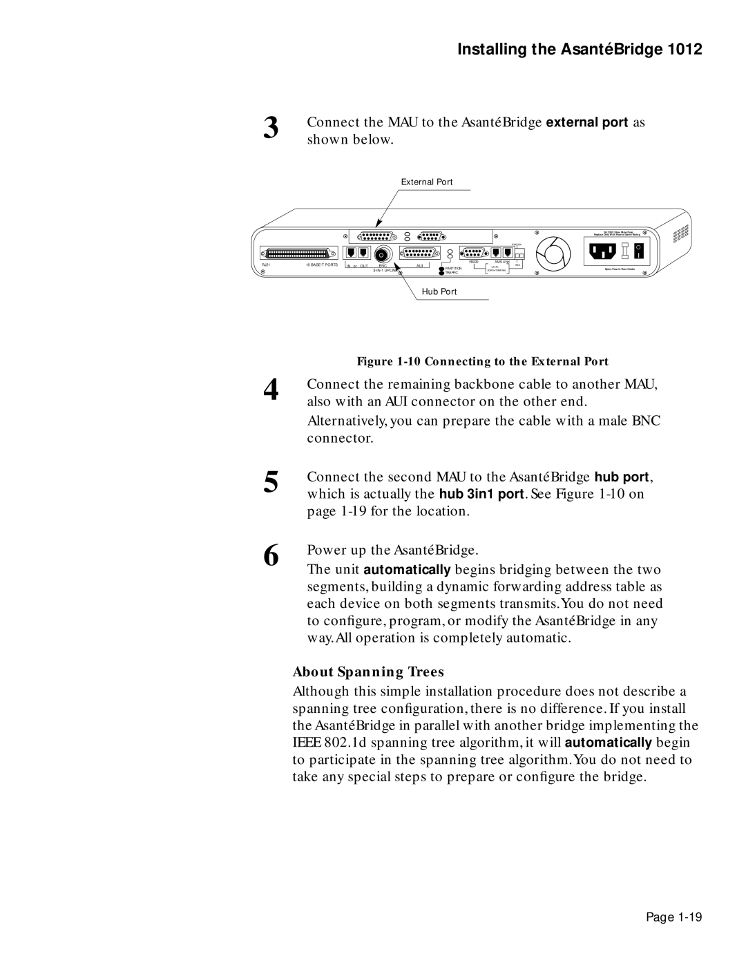
3 | Connect the MAU to the AsantéBridge external port as |
shown below. | |
| External Port |
| 2A/250V Slow Blow Fuse |
| Replace Only With Fuse of Same Rating |
RJ21 | 10 | IN or OUT | BNC | AUI |
![]()
|
| THROUGH | |
RS232 | AMS LINK | END | |
PARTITION | UP=PC | ||
Spare Fuse in Fuse Holder | |||
DOWN=TERMINAL | |||
TRAFFIC |
|
|
Hub Port
| Figure |
4 | Connect the remaining backbone cable to another MAU, |
also with an AUI connector on the other end. | |
| Alternatively, you can prepare the cable with a male BNC |
| connector. |
5 | Connect the second MAU to the AsantéBridge hub port, |
which is actually the hub 3in1 port. See Figure | |
| page |
6 | Power up the AsantéBridge. |
The unit automatically begins bridging between the two | |
| segments, building a dynamic forwarding address table as |
| each device on both segments transmits.You do not need |
| to configure, program, or modify the AsantéBridge in any |
| way.All operation is completely automatic. |
About Spanning Trees
Although this simple installation procedure does not describe a spanning tree configuration, there is no difference. If you install the AsantéBridge in parallel with another bridge implementing the IEEE 802.1d spanning tree algorithm, it will automatically begin to participate in the spanning tree algorithm.You do not need to take any special steps to prepare or configure the bridge.
Page