ASAI Installation
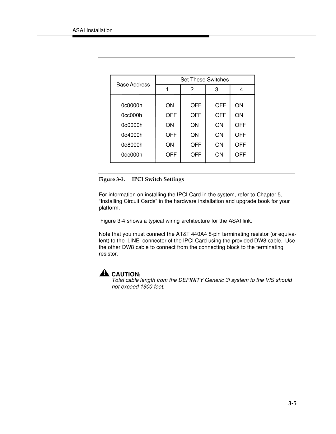
Base Address |
| Set These Switches |
| ||
|
|
|
| ||
1 | 2 | 3 | 4 | ||
| |||||
0c8000h | ON | OFF | OFF | ON | |
0cc000h | OFF | OFF | OFF | ON | |
0d0000h | ON | ON | ON | OFF | |
0d4000h | OFF | ON | ON | OFF | |
0d8000h | ON | OFF | ON | OFF | |
0dc000h | OFF | OFF | ON | OFF | |
|
|
|
|
| |
Figure 3-3. IPCI Switch Settings
For information on installing the IPCI Card in the system, refer to Chapter 5, “Installing Circuit Cards” in the hardware installation and upgrade book for your platform.
Figure 3-4 shows a typical wiring architecture for the ASAI link.
Note that you must connect the AT&T 440A4
!CAUTION:
Total cable length from the DEFINITY Generic 3i system to the VIS should not exceed 1900 feet.