Trigger and Remote Sensing Connections
A
Remote Sensing: sense ( + ) and sense ( - ) Used to connect the remote sensing leads to the power source.
TRIG IN: TRIG (IN) A
TRIG GND: TRIG ( ![]() ) Provides the common connection for the trigger signals.
) Provides the common connection for the trigger signals.
Turn-On Checkout
Introduction
Successful tests in this chapter provide a high degree of confidence that the electronic load is operating properly.
Checkout Procedure
The test in this section checks for proper operation of the electronic load. If you have not already done so, connect the power cord to the unit and plug it in.
Procedure |
|
| Display | Explanation | ||
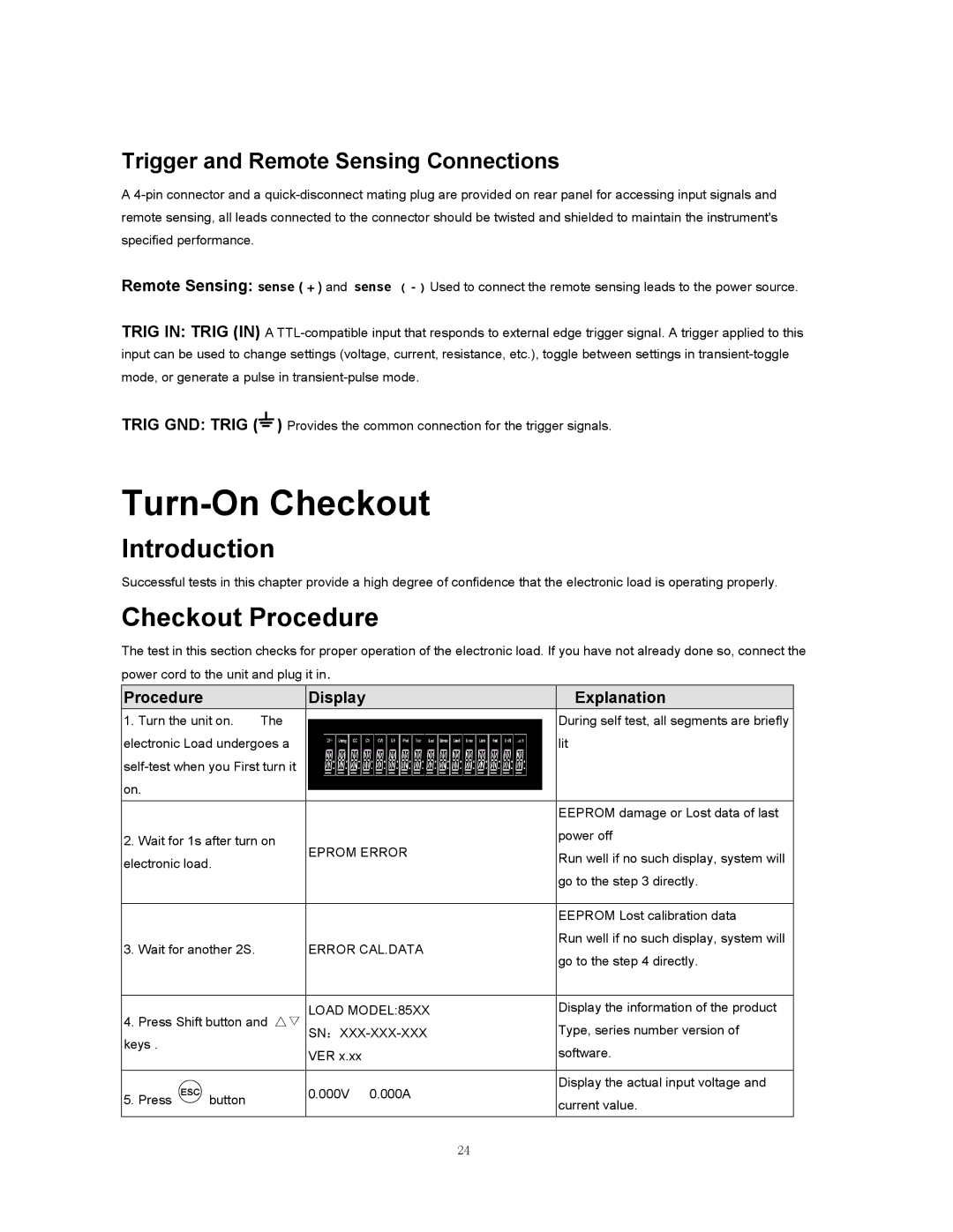
1. | Turn the unit on. | The |
| During self test, all segments are briefly | ||
electronic Load undergoes a |
| lit | ||||
|
| |||||
on. |
|
|
|
|
| |
|
|
|
|
|
|
|
|
|
|
|
|
| EEPROM damage or Lost data of last |
2. | Wait for 1s after turn on | EPROM ERROR | power off | |||
| ||||||
electronic load. |
| Run well if no such display, system will | ||||
|
| |||||
|
|
| ||||
|
|
|
|
|
| go to the step 3 directly. |
|
|
|
|
|
|
|
|
|
|
|
|
| EEPROM Lost calibration data |
3. | Wait for another 2S. |
| ERROR CAL.DATA | Run well if no such display, system will | ||
| go to the step 4 directly. | |||||
|
|
|
|
|
| |
|
|
|
|
|
|
|
4. | Press Shift button and △▽ | LOAD MODEL:85XX | Display the information of the product | |||
| Type, series number version of | |||||
keys . |
|
|
| VER x.xx | software. | |
|
|
|
|
| ||
|
|
|
|
|
|
|
|
| ESC |
|
| 0.000V 0.000A | Display the actual input voltage and |
5. | Press | button |
| current value. | ||
|
|
| ||||
|
|
|
|
|
| |
|
|
|
|
|
|
|
24