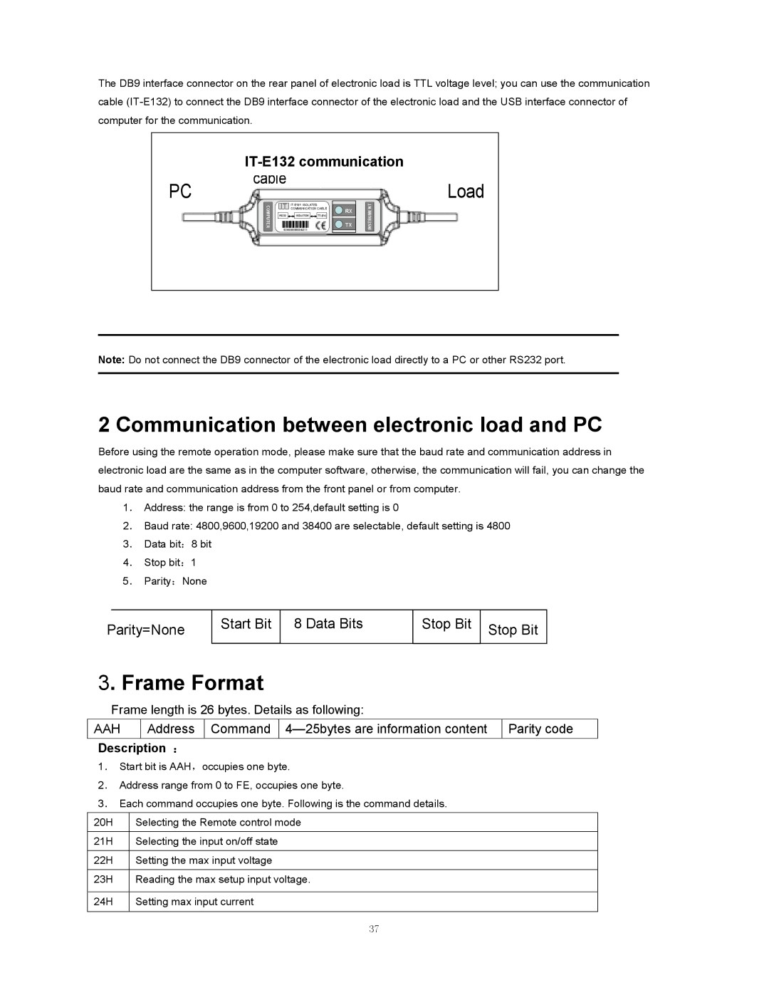
The DB9 interface connector on the rear panel of electronic load is TTL voltage level; you can use the communication cable
|
|
|
PC | cable | Load |
|
COMPUTER
IT
RS232 ![]() ISOLATION
ISOLATION ![]() TTL(5V)
TTL(5V)
859666668889942311
![]()
![]() RX
RX
![]()
![]() TX
TX
INSTRUMENT
Note: Do not connect the DB9 connector of the electronic load directly to a PC or other RS232 port.
2 Communication between electronic load and PC
Before using the remote operation mode, please make sure that the baud rate and communication address in electronic load are the same as in the computer software, otherwise, the communication will fail, you can change the baud rate and communication address from the front panel or from computer.
1. Address: the range is from 0 to 254,default setting is 0
2. Baud rate: 4800,9600,19200 and 38400 are selectable, default setting is 4800
3. Data bit:8 bit
4. Stop bit:1
5. Parity:None
Parity=None
Start Bit
8 Data Bits
Stop Bit | Stop Bit |
|
3. Frame Format
Frame length is 26 bytes. Details as following:
AAH
Address
Command
Parity code
Description :
1. Start bit is AAH,occupies one byte.
2. Address range from 0 to FE, occupies one byte.
3. Each command occupies one byte. Following is the command details.
20H | Selecting the Remote control mode |
|
|
21H | Selecting the input on/off state |
|
|
22H | Setting the max input voltage |
|
|
23H | Reading the max setup input voltage. |
|
|
24H | Setting max input current |
|
|
37
