| later location) |
|
|
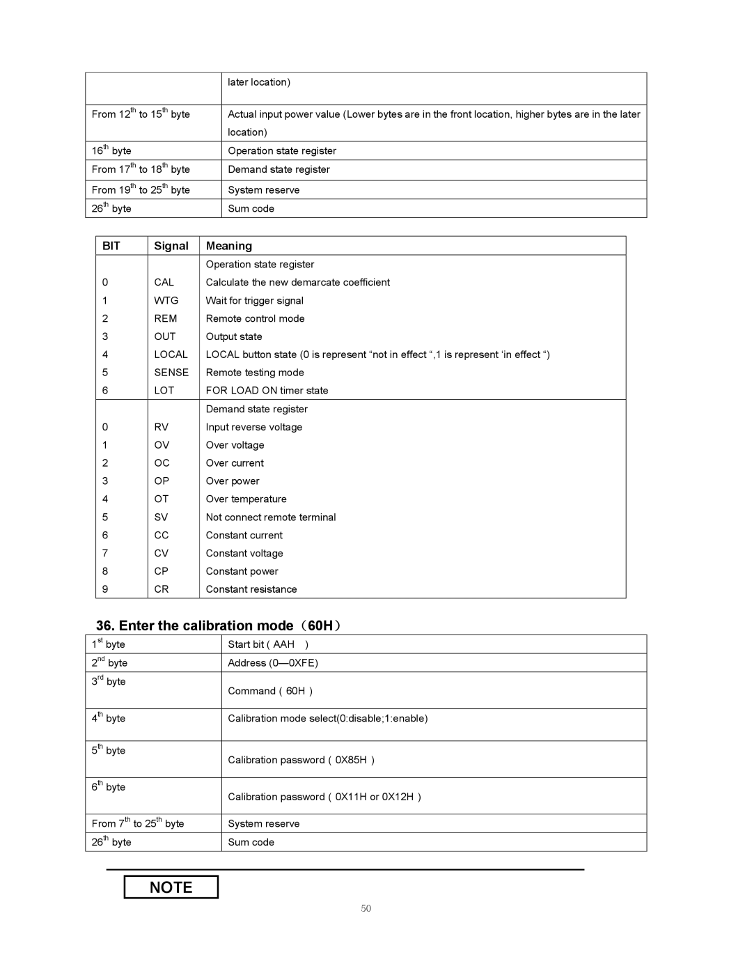
From 12th to 15th byte | Actual input power value (Lower bytes are in the front location, higher bytes are in the later |
| location) |
|
|
16th byte | Operation state register |
From 17th to 18th byte | Demand state register |
From 19th to 25th byte | System reserve |
26th byte | Sum code |
BIT | Signal | Meaning |
|
| Operation state register |
0 | CAL | Calculate the new demarcate coefficient |
1 | WTG | Wait for trigger signal |
2 | REM | Remote control mode |
3 | OUT | Output state |
4 | LOCAL | LOCAL button state (0 is represent “not in effect “,1 is represent ‘in effect “) |
5 | SENSE | Remote testing mode |
6 | LOT | FOR LOAD ON timer state |
|
|
|
|
| Demand state register |
0 | RV | Input reverse voltage |
1 | OV | Over voltage |
2 | OC | Over current |
3 | OP | Over power |
4 | OT | Over temperature |
5 | SV | Not connect remote terminal |
6 | CC | Constant current |
7 | CV | Constant voltage |
8 | CP | Constant power |
9 | CR | Constant resistance |
|
|
|
36. Enter the calibration mode(60H)
1st byte | Start bit ( AAH ) |
2nd byte | Address |
3rd byte | Command(60H) |
| |
|
|
4th byte | Calibration mode select(0:disable;1:enable) |
|
|
5th byte | Calibration password(0X85H) |
| |
|
|
6th byte | Calibration password(0X11H or 0X12H) |
| |
|
|
From 7th to 25th byte | System reserve |
26th byte | Sum code |
NOTE
50
