www.axxessid.com
Installation & User Guide
recommended that the segment address is 10.1.1.x Use the subnet mask as 255.255.255.0 and the gateway IP address should be 0.0.0.0
WAN Configuration
When working on a wide area network (WAN) all devices that are configured to operate with fixed IP address such as the AX200 controller, will probably have a different segment address. So if the Server (PC) IP address is 10.1.1.15 then the AX200 will require an IP address with the appropriate segment such as 10.1.2.52. Use the subnet mask as 255.255.255.0 and the gateway IP address must be configured (Please consult the Network Administrator for all IP Settings)
VPN Configuration
Generally configure Virtual Private networks as per the LAN Configuration setup. (Please consult the Network Administrator for all IP Settings)
Example IP Address Table
| Device Name |
|
| Location |
|
| IP Address |
|
| Gateway |
|
| Subnet Mask |
|
|
|
|
|
|
|
| Address |
|
| Address |
| |||
|
|
|
|
|
|
|
|
|
|
|
|
| ||
| File & Printer Server |
|
| London |
| 10.1.1.10 |
| 10.1.1.1 |
| 255.255.255.0 |
| |||
| Sales PC |
|
| London |
|
| DHCP |
|
| DHCP |
|
| DHCP |
|
| AX200 PC |
|
| London |
| 10.1.1.35 |
| 10.1.1.1 |
| 255.255.255.0 |
| |||
| AX200 Controller |
|
| London |
| 10.1.1.36 |
| 0.0.0.0 |
| 255.255.255.0 |
| |||
| AX200 Controller |
|
| London |
| 10.1.1.37 |
| 0.0.0.0 |
| 255.255.255.0 |
| |||
| File & Printer Server |
|
| New York |
| 10.1.2.10 |
| 10.1.2.1 |
| 255.255.255.0 |
| |||
| Sales PC |
|
| New York |
|
| DHCP |
|
| DHCP |
|
| DHCP |
|
| AX200 Controller |
|
| New York |
| 10.1.2.55 |
| 10.1.2.1 |
| 255.255.255.0 |
| |||
| AX200 Controller |
|
| New York |
| 10.1.2.56 |
| 10.1.2.1 |
| 255.255.255.0 |
| |||
A X 2 0 0 & i - B O X C o n n e c t i o n s
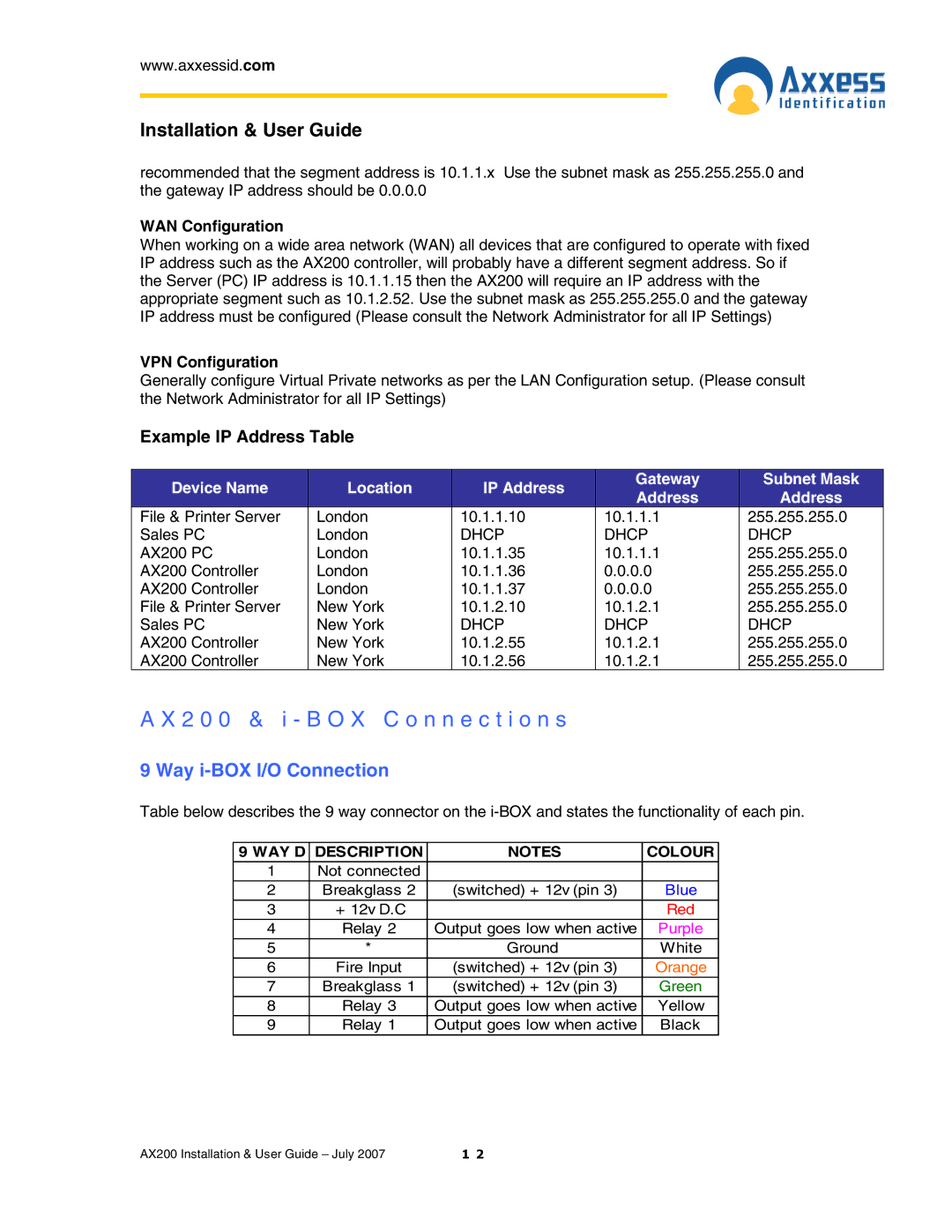
9 Way i-BOX I/O Connection
Table below describes the 9 way connector on the
9 WAY D | DESCRIPTION | NOTES | COLOUR |
1 | Not connected |
|
|
2 | Breakglass 2 | (switched) + 12v (pin 3) | Blue |
3 | + 12v D.C |
| Red |
4 | Relay 2 | Output goes low when active | Purple |
5 | * | Ground | White |
6 | Fire Input | (switched) + 12v (pin 3) | Orange |
7 | Breakglass 1 | (switched) + 12v (pin 3) | Green |
8 | Relay 3 | Output goes low when active | Yellow |
9 | Relay 1 | Output goes low when active | Black |
AX200 Installation & User Guide – July 2007 | 1 2 |