www.axxessid.com
Installation & User Guide
from the sensor, then add one to whatever the value of Gain is at that moment. For example if the sensor starts detecting the mains at Gain = 33, then the suitable sensitivity would be Gain = 34. If “Alarm on off” is ticked in the sensor’s settings; once the mains in the cable is lost; an alarm transaction will appear on the main screen stating the date & time and the type of the alarm. All the alarms and routine readings can be observed in the Reports section.
D T U ( D a t a T r a n s f e r U n i t )
Originally introduced as an AX100 component, the data transfer unit is available as an option, to transfer database changes from the PC to the controller without the need for a direct PC connection.
After the initial programming, the AX100 controller can be disconnected from the PC and the controller will perform all access control functions autonomously. The controller can open and close doors without computer intervention.
The PC is where all the system configuration and data management is stored. The optional data transfer unit (DTU) enables the data that has been entered at the PC to be downloaded to the controller without the need of a physical PC connection.
One data transfer unit can be used for up to 255 controllers, or a total of 16,000 cardholders distributed over multiple controllers in a single download. E.g. 10 controllers each with 1,600 cardholders can be downloaded in one go, without the need to go backwards and forwards between the PC and controller. Similarly 255 controllers each with 60 cardholders can be downloaded to each controller without returning to the PC. Only valid cardholders are downloaded to the controller.
The Data Transfer Unit is fully plug and play at the controller and PC. The AX200 PC software allows multiple DTU’s to be used.
Connecting the DTU
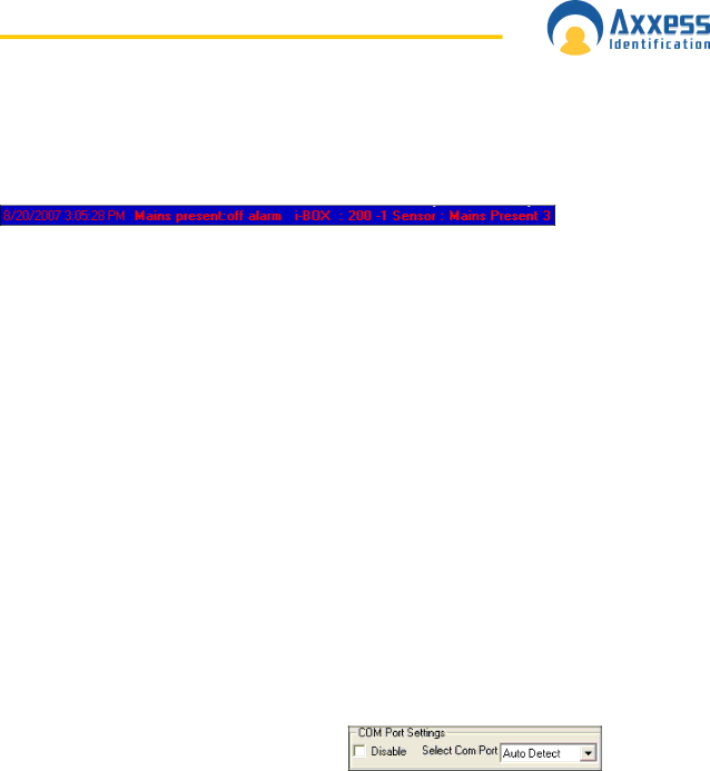
Make sure the COM port settings are enabled in System Settings • General Settings. Connect the power supply to the communication cable at the 15
way connector. Plug in the 9 way connector to the serial port of the PC. Start the AX200 software. Connect the DTU to the RJ45 connector, follow the
After configuring the DTU, the following window will appear on the screen. This window contains the list of the doors that require download.
AX200 Installation & User Guide – July 2007 | 1 0 3 |