www.axxessid.com
Installation & User Guide
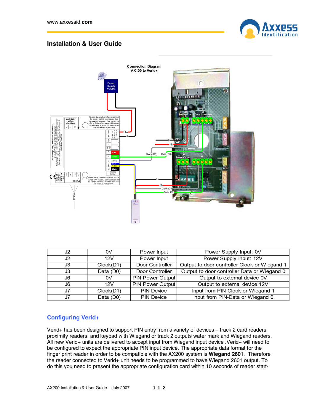
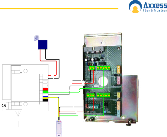
Connection Diagram
AX100 to Verid+
Power Supply +12VDC
+ -
.com |
| Lock Relay |
|
|
| To reset the electronic fuse, disconnect |
| |||
Power=VertGreen/OK/OK de puissance |
|
|
| the power, wait 30 seconds and then |
| |||||
784002 | NO | C | NC |
|
|
| D1LED0V | Black |
| |
www.axxessid |
|
| Gâche |
|
|
| reconnect the power. Pour remettre à |
| ||
|
| Electrique |
|
|
| zéro le fusible électronique, débranchez |
| |||
SeulementCCTension |
|
|
|
|
|
|
| la puissance, attendez 30 secondes et |
| |
|
|
|
|
|
|
| +12V0VREXC | In/Power Puissance DC>65mA |
| |
|
|
|
|
|
|
|
| puis rebranchez la puissance. |
| |
|
|
|
|
|
|
|
|
|
| +12v |
|
|
|
|
|
|
|
|
|
| 0v |
Only/ |
|
|
|
|
|
|
| Door C'tct |
| |
VoltageDC |
|
|
|
|
|
|
| D0 |
|
|
|
|
|
|
|
|
|
| +12V | Red |
|
|
|
|
|
|
|
|
|
| Green |
|
|
|
|
|
|
|
|
|
| White |
|
|
|
|
|
|
|
|
|
| Blue + |
|
(0)1793+44Tel: | 15max. metres toRS232 PC |
|
|
|
|
|
|
| Yellow |
|
N/A | 0V |
|
|
|
|
| Reader / |
| ||
|
|
|
| TX | RX |
|
|
| Lecteur |
|
|
|
|
|
|
|
|
|
| ||
|
|
|
|
| 3 | 2 | 5 | Reader wiring connections shown are for |
| |
|
|
|
|
| standard AX readers. Les raccordements |
| ||||
|
|
|
| W 9ay FD |
|
| de câblage de lecteur montrés sont pour |
| ||
|
|
|
|
|
|
|
| les lecteurs standard AX. |
| |
|
|
|
| AX200 |
|
|
|
|
|
|
J2 | J3 |
Power Input | Door Controller |
0v
|
|
| 12v |
|
|
| |
|
|
|
|
|
| J6 |
|
Clock (D1) | Data (D0) | J7 | |||||
|
|
|
|
|
| Power Output | |
|
|
|
|
|
|
| |
0v
12v
Clock (D1) Data (D0)
J2 | 0V | Power Input | Power Supply Input: 0V |
J2 | 12V | Power Input | Power Supply Input: 12V |
J3 | Clock(D1) | Door Controller | Output to door controller Clock or Wiegand 1 |
J3 | Data (D0) | Door Controller | Output to door controller Data or Wiegand 0 |
J6 | 0V | PIN Power Output | Output to external device 0V |
J6 | 12V | PIN Power Output | Output to external device 12V |
J7 | Clock(D1) | PIN Device | Input from |
J7 | Data (D0) | PIN Device | Input from |
Configuring Verid+
Verid+ has been designed to support PIN entry from a variety of devices – track 2 card readers, proximity readers, and keypad with Wiegand or track 2 outputs water mark and Wiegand readers. All new Verid+ units are delivered to accept input from Wiegand input device .Verid+ will need to be configured to expect the appropriate PIN input device. The appropriate data format for the finger print reader in order to be compatible with the AX200 system is Wiegand 2601. Therefore the reader connected to Verid+ unit needs to be programmed to have Wiegand 2601 output. To do this you need to present the appropriate configuration card within 10 seconds of reader start-
AX200 Installation & User Guide – July 2007 | 1 1 2 |