Chapter 3 Troubleshooting
Using DHCP Option 43
Using DHCP Option 43
You can use DHCP Option 43 to provide a list of controller IP addresses to the access points, enabling the access point to find and join a controller. Refer to the product documentation for your DHCP server for instructions on configuring DHCP Option 43. For additional information, refer to the “Configuring DHCP Option 43” section on page
Monitoring the Access Point LEDs
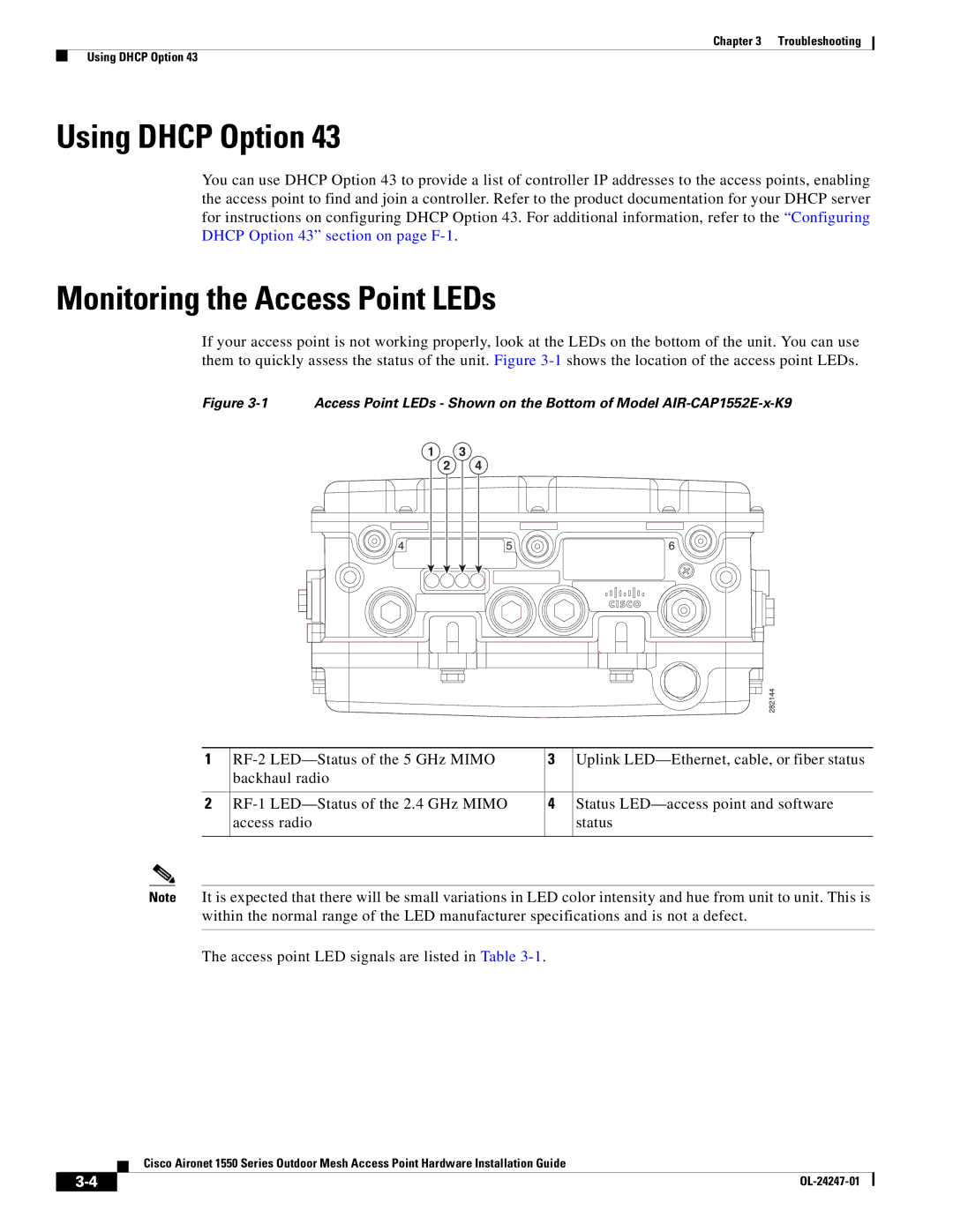
If your access point is not working properly, look at the LEDs on the bottom of the unit. You can use them to quickly assess the status of the unit. Figure
Figure 3-1 Access Point LEDs - Shown on the Bottom of Model AIR-CAP1552E-x-K9
1 | 3 |
|
2 | 4 |
|
4 | 5 | 6 |
|
| 282144 |
1 | 3 | Uplink | ||
| backhaul radio |
|
| |
|
|
|
|
|
2 | 4 | Status | ||
| access radio |
| status | |
|
|
|
|
|
Note It is expected that there will be small variations in LED color intensity and hue from unit to unit. This is within the normal range of the LED manufacturer specifications and is not a defect.
The access point LED signals are listed in Table
Cisco Aironet 1550 Series Outdoor Mesh Access Point Hardware Installation Guide
|
| |
|