Americas Headquarters
April Revised February 20
Cisco Systems, Inc 170 West Tasman Drive San Jose, CA
800 553-NETS Fax 408
Turn the television or radio antenna until the interference stops
Objectives
Connectors
C O N T E N T S
Preface
GPS Option
Mounting Bracket Assembly on a Pole
Warnings
Assembling the Pole Clamp Bracket and the Mounting Bracket
Troubleshooting
Antenna N-Type Connector Locations
Connecting a Fiber-Optic Cable to the Access Point
Adding the Access Point MAC Addresses to the Controller Filter List
Connecting the Backup Battery Cable and Closing the Radio Cover
Before Beginning the Installation or Replacement
93/42/EEC
English Translation B-12
Operation of Cisco Aironet Access Points in Brazil B-11
Access Point Pinouts E-1
EU Declaration of Conformity B-11
Contents
viii
OL-24247-01
Objectives
Preface
Audience
Backup Battery
Installing the Access Point
Troubleshooting
Installing or Replacing the
italic screen font
Varoitus TÄRKEITÄ TURVALLISUUSOHJEITA
Aviso INSTRUÇÕES IMPORTANTES DE SEGURANÇA
xiii
Este símbolo de aviso significa perigo. Você se encontra em uma situação em que há risco de lesões corporais. Antes de trabalhar com qualquer equipamento, esteja ciente dos riscos que envolvem os circuitos elétricos e familiarize-se com as práticas padrão de prevenção de acidentes. Use o número da declaração fornecido ao final de cada aviso para localizar sua tradução nos avisos de segurança traduzidos que acompanham o dispositivo
OL-24247-01
Running H/F Running H/F
Finding the Product Serial Number
Related Documents
xvii
Obtaining Documentation, Support, and Security Guidelines
Running H/F Running H/F
xviii
OL-24247-01
C H A P T E R
About the 1552 Access Point
Hardware Models, page Hardware Features, page
Overview
less/ps5679/ps5861/productdatasheet0900aecd
Hardware Models
80537b6a.html
80537b6a.html
less/ps5679/ps5861/productdatasheet0900aecd
Antennas
Battery Backup Option
Power Options
Regulatory Domains
Multiple Radio Operation, page Antenna Configurations, page
Hardware Features
Connectors
Connectors, page Antenna Port Locations, page
Connectors
1552E/1552EU Connectors
Chapter 1 Overview Hardware Features
Console port
Not used
Access Point Model AIR-CAP1552EU-x-K9 Top Connectors
1552C/1552CU Connectors
1552I Connectors
Access Point Model AIR-CAP1552I-x-K9 Bottom Connectors
Figure 1-7 Access Point Model AIR-CAP1552CU-x-K9 Top Connectors
AIR-CAP1552CU-x-K9
Connectors for All Models
1-10
Figure 1-9 Access Point DC Power Connector and Ground Lug All Models
1-11
Antenna Port Locations
1-12
Multiple Radio Operation
Low Profile Dual-Band 2.4/5-GHz Omni Antenna Array
Antenna Configurations
1-13
1-14
Cisco Aironet Dual-Band Omnidirectional Antenna AIR-ANT2547V-N
1-15
1-16
AIR-CAP1552EU-x-K9 and AIR-CAP1552CU-x-K9
1-17
Cisco Aironet 2.4-GHz 5-dBi Omnidirectional Antenna AIR-ANT2450V-N
Cisco Aironet 2.4-GHz 2-dBi Omnidirectional Antenna AIR-ANT2420V-N
1-18
1-19
Cisco Aironet 2.4-GHz 8-dBi Omnidirectional Antenna AIR-ANT2480V-N
Cisco Aironet 5-GHz 8-dBi Omnidirectional Antenna AIR-ANT5180V-N
Cisco Aironet 5-GHz 4-dBi Omnidirectional Antenna AIR-ANT5140V-N
1-20
1-21
Multiple Power Sources
Ethernet PoE Ports
Cable Modem POC
1-22
1-23
Fiber Option
Warning Class 1 laser product. Statement
1-24
GPS Option
Metal Enclosure
Optional Hardware
1-25
Wireless Backhaul
Network Deployment Examples
Point-to-Point Bridging
Figure 1-24 Access Point to Multipoint Bridging Example
Point-to-Multipoint Bridging
1-26
Figure 1-23 Access Point Point-to-Point Bridging Example
1-27
Point-to-Multipoint Mesh Network
Figure 1-25 Typical Mesh Configuration Using Access Points
1-28
Layer 3 Network Operation
Avoiding Damage to Radios in a Testing Environment, page
Installing the Access Point
Unpacking the Access Point, page Tools and Hardware, page
Warnings, page Safety Information, page
Cable Strand Installation Hardware and Tools, page
Unpacking the Access Point
Package Contents
Pole Installation Hardware and Tools, page
Optional Tools and Hardware That You Supply
Pole Installation Hardware and Tools
Warnings
Cable Strand Installation Hardware and Tools
SAVE THESE INSTRUCTIONS
FCC Safety Compliance Statement
Safety Information
Safety Precautions
Warning The AC power supply has double pole/neutral fusing. Statement
Avoiding Damage to Radios in a Testing Environment
Site Surveys
Installation Guidelines
Becoming Familiar with Access Point Installation Components
Before Beginning the Installation
Building roof-overhang
2-10
Figure 2-2 Pole Mount Installation
2-11
Cable Strand Mounting Kit brackets
2-12
Closing the Access Point Hinged Cover
Opening the Access Point Hinged Cover
2-13
Installation Options
Mounting the Access Point
2-14
Installing the Mounting Bracket on a Wall All Models, page
Access Point Mounting Orientation
Installing the Mounting Bracket on a Wall All Models
Access Point Mounting Orientation, page
Materials Required
2-16
In Kit
Access point quick mount notches
2-17
Assembling the Pole Clamp Bracket and the Mounting Bracket
Installing the Mounting Bracket on a Pole All Models
2-18
M8 x1.25x16 bolts with lock washers
2-19
2-20
Mounting Bracket Assembly on a Pole
Material Needed to Mount Access Point on a Pole
2-21
Metal strap open space
2-22
2-23
Installing 1552E, 1552EU, or 1552I in the Mounting Bracket
345827
2-24
Figure 2-14 Location of Access Point Top Support Bolt Hole on
Chapter 2 Installing the Access Point Mounting the Access Point
Figure 2-15 Access Point 1552E/1552EU Hanging in Mounting Bracket
2-25
Cable Strand Mounting the 1552C or 1552CU Access Point, page
Installing 1552C or 1552CU in the Mounting Bracket
Cable Strand Mounting the 1552C or 1552CU Access Point
2-26
To mount the access point, follow these steps
2-27
M8 x16 bolts with lock washers
2-28
Figure 2-19 Attach the Cable Strand to the Cable Mount Brackets
2-29
2-30
Mounting the 1552C or 1552CU Access Point on a Pole/Wall
Unused
2-31
2-32
Figure 2-23 Mounting Bracket Position for Vault Mounting
2-33
Figure 2-24 Attaching Grounding Lug to Grounding Point
2-34
Figure 2-25 1552C Access Point Facing Up in Vault Location
2-35
Product ID
Installing Antennas
2-36
Frequency
2-37
Antenna N-Type Connector Locations
Figure 2-26 Antenna Port Locations - Model AIR-CAP1552E-x-K9
2-38
Antenna Mounting Options
Figure 2-29 AIR-CAP1552E-x-K9
2-39
Chapter 2 Installing the Access Point Installing Antennas
Figure 2-28 AIR-CAP1552C-x-K9 and AIR-CAP1552I-x-K9
AIR-ANT5180V-N AIR-ANT2450V-N or AIR-ANT2480V-N
2-40
2-41
Grounding the Access Point
Safety Precautions
2-42
Connecting a Fiber-Optic Cable to the Access Point
Figure 2-32 Fiber-Optic Cable Components
2-43
Thread end
2-44
120 VAC-Connecting an AC Power Cable to the Access Point, page
Powering the Access Point
Connecting a 1500 Series Power Injector
Connecting a 1500 Series Power Injector, page
Step 7 Continue with What to Do Next, page
Connecting an Ethernet Cable to the Access Point
2-46
AIR-CAP1552EU-x-K9
2-47
Figure 2-35 liquid-tight Adapter
2-48
2-49
Cord Diameter
2-50
AC Power Cord
AC Power Cord Information
Statement
Connecting Streetlight AC Power
2-51
Figure 2-38 Using the Streetlight Power Tap Adapter
2-52
Figure 2-39 AC Power Connector - Shown on Access Point Model AIR-CAP1552E-x-K9
2-53
2-54
Connecting an AC Power Cable to the Access Point
Statement
2-55
Connecting a DC Power Cable to the Access Point
Figure 2-41 Location of the DC Power Liquid-Tight Adapter
2-56
Figure 2-42 Liquid-Tight Adapter
Securing screws
2-57
2-58
Connecting a Cable POC Power to the Access Point
Figure 2-45 RF Splitter Components
2-59
Adding the Access Point MAC Addresses to the Controller Filter List
Configuring the Access Point
2-60
2-61
Configuring a RAP
Configuring a Bridge Group Name
Step 2 Choose SECURITY MAC Filtering New
The BGN is a string of ten characters maximum. A factory-set bridge group name NULL VALUE is assigned during manufacturing. It is not visible to you, but allows new access point radios to join a network of new access points. The BGN can be reconfigured from the Controller CLI and GUI. After configuring the BGN, the access point reboots
2-62
2-63
What to Do Next
Step 5 Click Apply
Chapter 2 Installing the Access Point What to Do Next
2-64
OL-24247-01
Monitoring the Access Point LEDs, page
Troubleshooting
Guidelines for Using the Access Points, page
Controller MAC Filter List, page Using DHCP Option 43, page
Convergence Delays
Guidelines for Using the Access Points
Important Notes
MAP Data Traffic
Controller MAC Filter List
Bridge Loop
Controller DHCP Server
Monitoring the Access Point LEDs
Using DHCP Option
Color1
Verifying Controller Association
Meaning
Changing the Bridge Group Name
Connecting to the Access Point Locally
AIR-CAP1552EU-x-K9
AIR-CAP1552CU-x-K9, and AIR-CAP1552I-x-K9
Figure 3-4 Power Injector Connectors and LEDs
Access Point Power Injector
Monitoring the Power Injector LEDs
Using the Reset Button
Disabling Backup Battery Power
Reboot the Access Point
3-10
Note The battery backup unit is reactivated when the access point is rebooted power cycled again
3-11
Chapter 3 Troubleshooting Using the Reset Button
3-12
OL-24247-01
Removing a Backup Battery, page Installing a New Backup Battery, page
Installing or Replacing the Backup Battery
Before Beginning the Installation or Replacement, page
Opening the Access Point Radio Cover, page
Before Beginning the Installation or Replacement
Opening the Access Point Radio Cover
Removing a Backup Battery
Figure 4-3 Backup Battery Screws
Installing a New Backup Battery
What to Do Next
Connecting the Backup Battery Cable and Closing the Radio Cover
Figure 4-4 Radio Cover Screw Tightening Sequence
A P P E N D I X A
Translated Safety Warnings
Step 5 Click Install and Upgrade
Step 6 Click Install and Upgrade Guides
OL-24247-01
Appendix A Translated Safety Warnings
Declaration of Conformity for RF Exposure, page B-7
Declarations of Conformity and Regulatory Information
A P P E N D I X B
Industry Canada, page B-3
Tested To Comply With FCC Standards FOR HOME OR OFFICE USE
Models
FCC Certification number
Manufacturer
IC Certification Number
Industry Canada
Declaration of Conformity for RF Exposure
Canadian Compliance Statement
European Community, Switzerland, Norway, Iceland, and Liechtenstein
Access Point Models
OL-24247-01
Appendix B Declarations of Conformity and Regulatory Information
Page
Australia
United States
Canada
European Union
Guidelines for Operating Cisco Aironet Access Points in Japan
Lightweight Access Point Model
Japanese Translation
English Translation
VCCI Statement for Japan
Administrative Rules for Cisco Aironet Access Points in Taiwan
Chinese Translation
B-10
Chinese Translation English Translation
English Translation
EU Declaration of Conformity
Operation of Cisco Aironet Access Points in Brazil
Statement 371-Power Cable and AC Adapter
Access Point Models
English Translation
Regulatory Information
Portuguese Translation
B-12
Step 5 Click Install and Upgrade
Channels and Power Levels
Step 3 Click Wireless
A P P E N D I X C
OL-24247-01
Appendix C Channels and Power Levels
see Table D-2 and
Access Point Specifications
Table D-3 for power
A P P E N D I X D
Table D-1
Access Point Specifications continued
Category
Category
Specifications
Optional components
Total Power Consumption
Total power budget when using DC power source
Total power budget when using POC power source
Total power budget when using AC power source
40-MHz Rate Mbps
MCS Index
GI 2 = 800ns
GI = 400ns
OL-24247-01
Appendix D Access Point Specifications
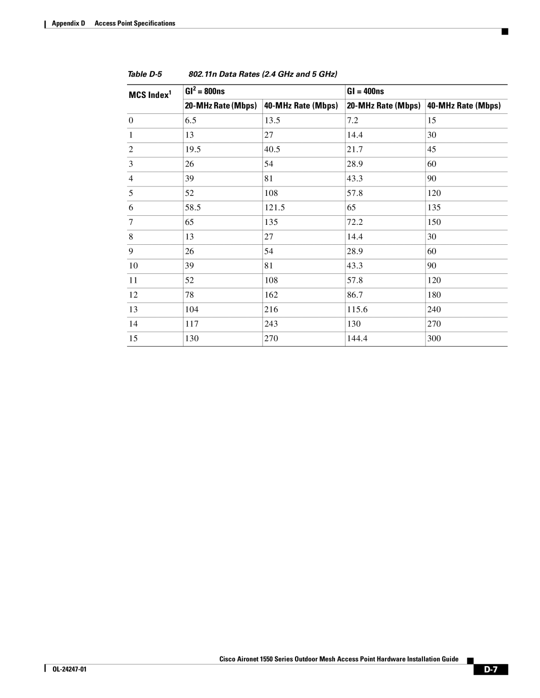
A P P E N D I X E
Access Point Pinouts
Table E-4
Power Injector Input Connector To Switch Pinouts
Power Injector Output Connector To AP Pinouts
Table E-3
A P P E N D I X F
Configuring DHCP Option
Overview, page F-2
Access Point
Overview
Vendor Class Identifier VCI
Configuring Option 43 for 1000, 1500, and 1550 Series Access Points
Type + Length + Value
GL-1
G L O S S A R Y
GL-2
GL-3
A device that connects two otherwise incompatible networks together
GL-4
GL-5
GL-6