Chapter 2 Installing the Access Point
Installing Antennas
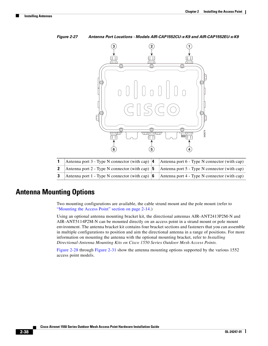
Figure 2-27 Antenna Port Locations - Models AIR-CAP1552CU-x-K9 and AIR-CAP1552EU-x-K9
3 | 2 | 1 |
|
|
| 345674 |
| 6 | 5 | 4 |
1 | Antenna port 3 - Type N connector (with cap) | 4 | Antenna port 6 - Type N connector (with cap) |
2 | Antenna port 2 - Type N connector (with cap) | 5 | Antenna port 5 - Type N connector (with cap) |
3 | Antenna port 1 - Type N connector (with cap) | 6 | Antenna port 4 - Type N connector (with cap) |
Antenna Mounting Options
Two mounting configurations are available, the cable strand mount and the pole mount (refer to “Mounting the Access Point” section on page
Using an optional antenna mounting bracket kit, the directional antennas
Figure 2-28 through Figure 2-31 show the antenna mounting options supported by the various 1552 access point models.
| Cisco Aironet 1550 Series Outdoor Mesh Access Point Hardware Installation Guide |