Chapter 1 Preparing for Installation
Site Requirement Guidelines
NEBS Supplemental Unit Bonding and Grounding Guidelines
You must permanently connect the central office ground system or interior equipment grounding system to the supplemental bonding and grounding connection on the side of the router chassis to meet network equipment building system (NEBS) requirements as well as safety compliance requirements. These grounding points are referred to as the NEBS bonding and grounding points.
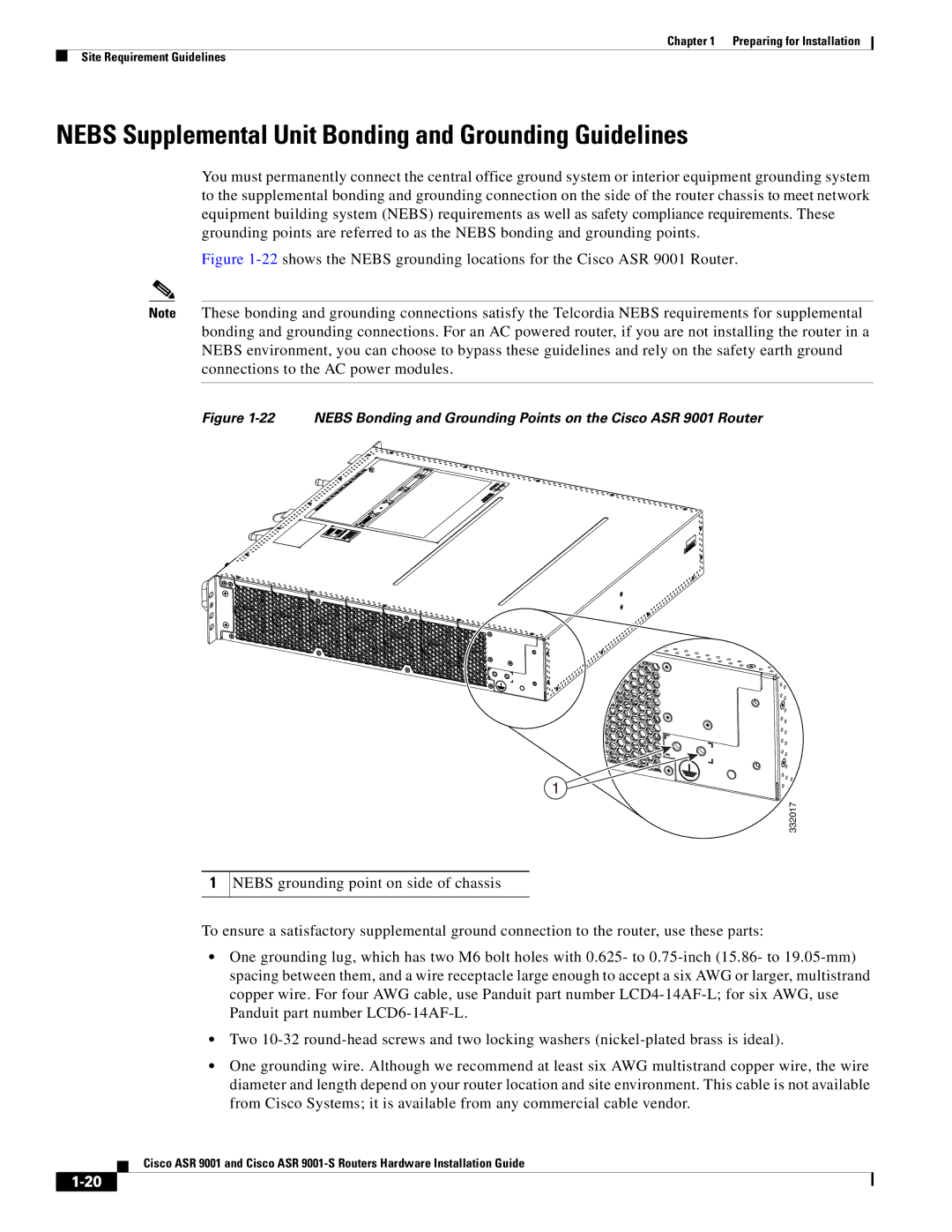
Figure 1-22 shows the NEBS grounding locations for the Cisco ASR 9001 Router.
Note These bonding and grounding connections satisfy the Telcordia NEBS requirements for supplemental bonding and grounding connections. For an AC powered router, if you are not installing the router in a NEBS environment, you can choose to bypass these guidelines and rely on the safety earth ground connections to the AC power modules.
Figure 1-22 NEBS Bonding and Grounding Points on the Cisco ASR 9001 Router
1
332017
1
NEBS grounding point on side of chassis
To ensure a satisfactory supplemental ground connection to the router, use these parts:
•One grounding lug, which has two M6 bolt holes with 0.625- to
•Two
•One grounding wire. Although we recommend at least six AWG multistrand copper wire, the wire diameter and length depend on your router location and site environment. This cable is not available from Cisco Systems; it is available from any commercial cable vendor.
Cisco ASR 9001 and Cisco ASR