Chapter 4 Troubleshooting the Installation
Troubleshooting the Route Processor Subsystem
| Table | RP Discrete LED Display Definitions (continued) | |||
|
|
|
|
|
|
Indicator (Label) |
| LED |
| Color | Description |
|
|
|
|
|
|
Fan Tray |
|
|
|
|
|
|
|
|
|
|
|
STATUS |
|
| Amber | Fan tray power ON state. | |
(Fan tray) |
|
|
|
|
|
|
|
| Green | Fan tray fully functional. | |
|
|
|
|
|
|
|
|
|
| Red | Fan failure condition. |
|
|
|
|
|
|
Ethernet Ports and Status LEDs
The RP has two
The transmission speed of the Ethernet port is not
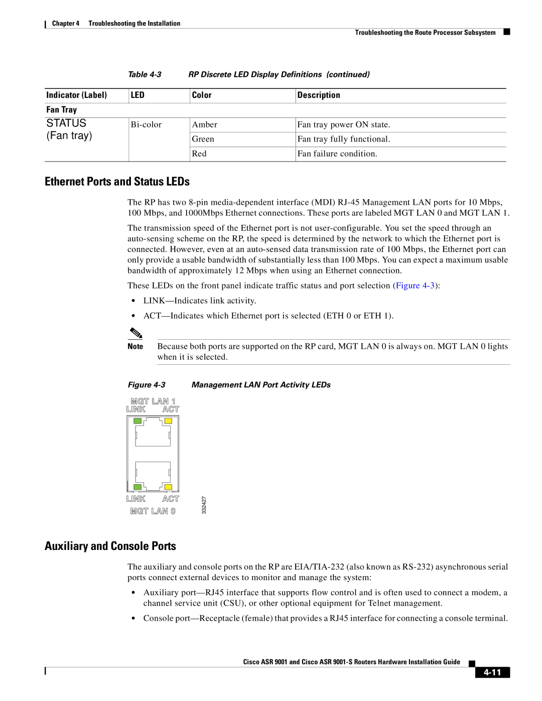
These LEDs on the front panel indicate traffic status and port selection (Figure
•
•
Note Because both ports are supported on the RP card, MGT LAN 0 is always on. MGT LAN 0 lights when it is selected.
Figure 4-3 Management LAN Port Activity LEDs
332427
Auxiliary and Console Ports
The auxiliary and console ports on the RP are
•Auxiliary
•Console
Cisco ASR 9001 and Cisco ASR
