Chapter 1 Overview
Optional Expansion Modules
Module Features
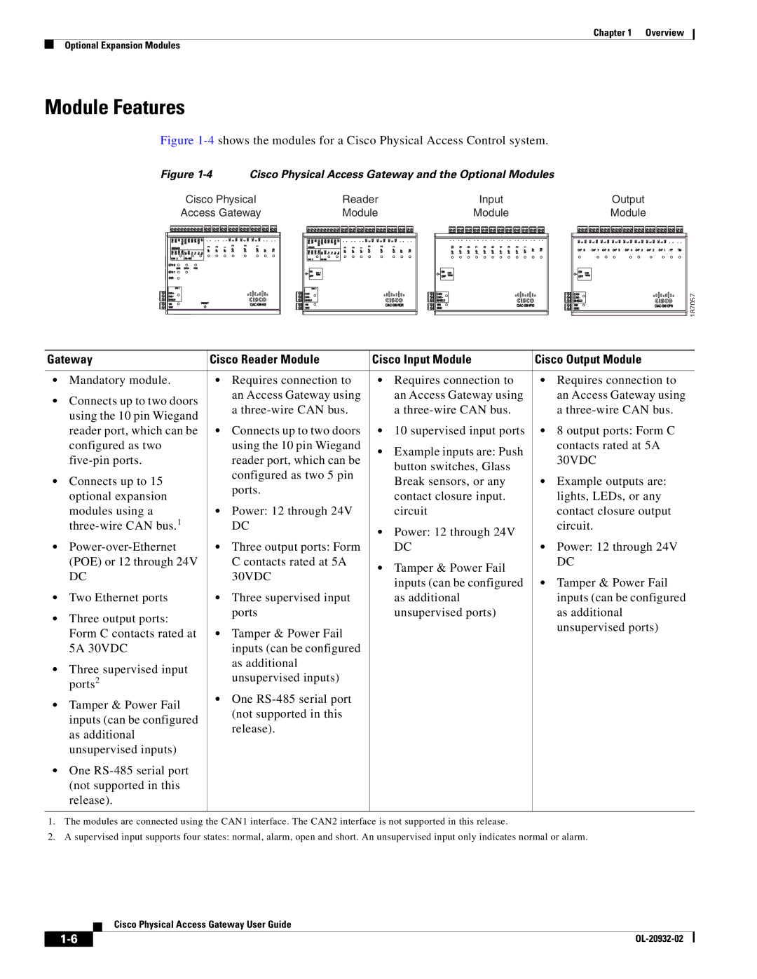
Figure 1-4 shows the modules for a Cisco Physical Access Control system.
Figure 1-4 Cisco Physical Access Gateway and the Optional Modules
Cisco Physical | Reader | Input | Output |
Access Gateway | Module | Module | Module |
187057
Gateway | Cisco Reader Module | Cisco Input Module | Cisco Output Module | ||||
|
|
|
|
|
|
|
|
• | Mandatory module. | • | Requires connection to | • | Requires connection to | • | Requires connection to |
• Connects up to two doors |
| an Access Gateway using |
| an Access Gateway using |
| an Access Gateway using | |
| a |
| a |
| a | ||
| using the 10 pin Wiegand |
|
|
| |||
|
|
|
|
|
|
| |
| reader port, which can be | • Connects up to two doors | • | 10 supervised input ports | • 8 output ports: Form C | ||
| configured as two |
| using the 10 pin Wiegand | • | Example inputs are: Push |
| contacts rated at 5A |
|
| reader port, which can be |
| 30VDC | |||
|
|
| button switches, Glass |
| |||
|
|
| configured as two 5 pin |
|
|
| |
• Connects up to 15 |
|
| Break sensors, or any | • | Example outputs are: | ||
| ports. |
| |||||
| optional expansion |
|
| contact closure input. |
| lights, LEDs, or any | |
|
|
|
|
| |||
| modules using a | • Power: 12 through 24V |
| circuit |
| contact closure output | |
|
| DC | • | Power: 12 through 24V |
| circuit. | |
|
|
|
|
|
| ||
• | • Three output ports: Form |
| DC | • Power: 12 through 24V | |||
| (POE) or 12 through 24V |
| C contacts rated at 5A | • | Tamper & Power Fail |
| DC |
| DC |
| 30VDC |
|
| ||
|
|
| inputs (can be configured | • Tamper & Power Fail | |||
|
|
|
|
| |||
• | Two Ethernet ports | • | Three supervised input |
| as additional |
| inputs (can be configured |
• | Three output ports: |
| ports |
| unsupervised ports) |
| as additional |
|
|
|
|
| unsupervised ports) | ||
| Form C contacts rated at | • Tamper & Power Fail |
|
|
| ||
|
|
|
|
| |||
| 5A 30VDC |
| inputs (can be configured |
|
|
|
|
• | Three supervised input |
| as additional |
|
|
|
|
| unsupervised inputs) |
|
|
|
| ||
| ports2 |
|
|
|
|
| |
• Tamper & Power Fail | • One |
|
|
|
| ||
| (not supported in this |
|
|
|
| ||
| inputs (can be configured |
|
|
|
|
| |
|
| release). |
|
|
|
| |
| as additional |
|
|
|
|
| |
|
|
|
|
|
|
| |
| unsupervised inputs) |
|
|
|
|
|
|
• One |
|
|
|
|
|
| |
| (not supported in this |
|
|
|
|
|
|
| release). |
|
|
|
|
|
|
|
|
|
|
|
|
|
|
1.The modules are connected using the CAN1 interface. The CAN2 interface is not supported in this release.
2.A supervised input supports four states: normal, alarm, open and short. An unsupervised input only indicates normal or alarm.
Cisco Physical Access Gateway User Guide
| ||
|