Chapter 4 Connecting a Cisco Input Module
Physical Overview and Port Description
•Connector plugs:
Type
3 Pin
2 Pin
Quantity
1
13
Physical Overview and Port Description
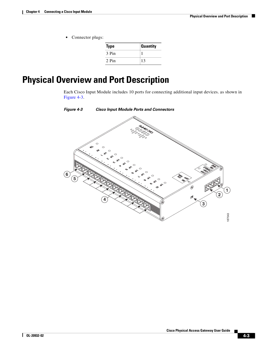
Each Cisco Input Module includes 10 ports for connecting additional input devices. as shown in Figure
Figure 4-3 Cisco Input Module Ports and Connectors
6
5
1
![]() 2 4
2 4![]()
3
187043
Cisco Physical Access Gateway User Guide
|
| ||
|
|