Chapter 3 Connecting a Cisco Reader Module
Physical Overview and Port Description
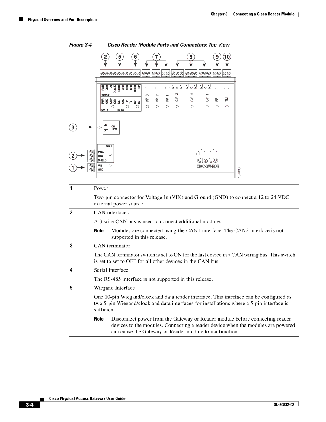
Figure 3-4 Cisco Reader Module Ports and Connectors: Top View
3
2![]()
1![]()
1
2
3
4
5
2 | 5 | 6 | 7 | 8 | 9 | 10 |
187038
Power
CAN interfaces
A
Note Modules are connected using the CAN1 interface. The CAN2 interface is not supported in this release.
CAN terminator
The CAN terminator switch is set to ON for the last device in a CAN wiring bus. This switch is set to set to OFF for all other devices in the CAN bus.
Serial Interface
The
Wiegand Interface
One
Note Disconnect power from the Gateway or Reader module before connecting reader devices to the modules. Connecting a reader device when the modules are powered can cause the Gateway or Reader module to malfunction.
Cisco Physical Access Gateway User Guide
| ||
|